D i d o H a r d w a r e M a n u a l
v . 1 . 0 . 5
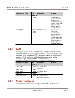
The following table describes the interface signals:
Connector Pin
Pin
name
Function
Notes
KP_ROW0
J1.72
Keypad row 0
KP_ROW1
J1.73
Keypad row 1
KP_ROW2
J1.74
Keypad row 2
KP_ROW3
J1.75
Keypad row 3
KP_ROW4
J1.80
Keypad row 4
KP_ROW5
J1.78
Keypad row 5
KP_ROW6
J1.86
Keypad row 6
KP_ROW7
J1.77
Keypad row 7
KP_COL0
J1.82
Keypad column 0
KP_COL1
J1.81
Keypad column 1
KP_COL2
J1.84
Keypad column 2
KP_COL3
J1.83
Keypad column 3
KP_COL4
J1.79
Keypad column 4
KP_COL5
J1.88
Keypad column 5
KP_COL6
J1.85
Keypad column 6
KP_COL7
J1.106 Keypad column 7
7.13
PCI Express
The device supports connections to PCIe-compliant devices via
the integrated PCIe master/slave bus interface. The PCIe
module is comprised of a dual-mode PCIe core and a SerDes
PHY. The device implements a single one-lane PCIe 2.0 (5.0
GT/s) Endpoint/Root Complex port. Please note that AC
decoupling capacitors are integrated on DIDO, with the
following configuration:
●
100 nF in series with the TX pair lines
●
270 pF in series with the SERDES_CLK pair lines
The following table describes the interface signals:
August, 2014
66/78

