Operation of the Alarm Output Module
Page 11
Connecting the Outputs
The output devices are photo-coupled MOS transistors. They provide floating
“contacts” suitable for low-voltage AC or DC loads, as specified in “Contact
Specifications” on page 6. Each output contact is connected between the two
like-colored terminals (A, B, etc.) of terminal block J4 (labelled CONTACTS).
To make connection to the outputs install the two wires from the external circuit,
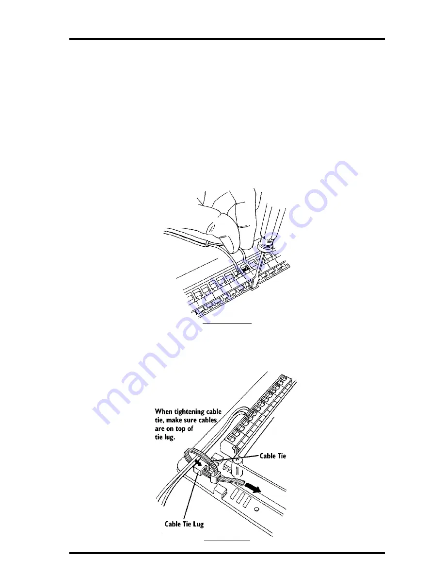
one to each terminal of the pair, in J4. To place wires into the cage clamp, strip
about 5/16” (8 mm) of the insulation off each wire in the cable. Use a small
screwdriver to push down on the lever next to the cage clamp, insert the exposed
wire into the opening created, and release the lever. When you release the lever,
the wire(s) will be held in place by the cage clamp If the external load voltage is
DC, insert the more-positive voltage wire in the + side of the terminal pair.
I
NSTALLING
W
IRES
When finished, gather all wires together and secure them to the cable tie lug
using a cable tie. as shown below. When tightening the cable tie, make sure the
wires are on top of the lug.
S
ECURING
W
IRES


