Alarm Output Module Operation
Page 5
A
LARM
O
UTPUT
M
ODULE
O
PERATION
The section below provides technical information on the operation of the
Alarm Output Module. Installation instructions appear separately below.
Circuit Operation
AOM C
IRCUIT
D
IAGRAM
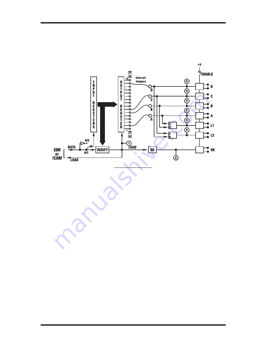
The Console sends to the Sensor Interface Module (SIM) a serial data word
containing one bit for each alarm signal and user- and system-controlled out-
put. From the SIM (or the Interface Cable Adapter Module) this is sent to the
Alarm Output Module. The data are sent twice, once in true form and once
inverted, and are shifted into the AOM’s Input Register.
When the Verify circuit confirms that the correct number of bits has been sent
and that the two data sets match correctly, it generates a LOAD pulse to trans-
fer the data into the Output Register. All 16 bits of this register are available at
terminal strip J3 for selection as outputs. Four of the 16 are jumper-selected by
the user to drive the photo-coupled outputs and appear as contact closures A,
B, C, and D (closure indicated by lighted red LEDs).
Setting the ENABLE switch off causes all contacts to open (the LEDs continue
to indicate the state of the selected alarms).
The LOAD command pulse is sent back to the Console, where “quality of data
transfer” is determined and sent to the Link software. LOAD also flashes the
yellow indicator to show that a good transfer has occurred.
Two Set/Reset (RS) Flip-flops can be used to latch the four outputs. Latch 1 is SET
by output A and RESET by B. Latch 2 is SET by output C and RESET by D. The
Latch contents are available as output contact closures L1 and L2 (set ON = closed).
The OK circuits check that a good transfer has occurred within the past 10 sec-
onds or so, that the power voltage is good, and that the ENABLE switch is on.
This validity check result is indicated by the green LED and is available as the
OK output contact (OK = closed).


