Page 7
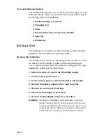
Step 4: Connect the Harness Cable to the 3 Main Tap Wires
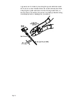
Use the butt splice to connect the VSS in-line circuit input
wires to your three main tap wires (+12V, Ground, VSS) by
matching the wire colors. Red is used for +12V, black for the
ground wire, and white for the VSS wire. Make sure the wiring
harness extends to where you can plug the DriveRight display
into it. Once the harness cable is connected, install the fuse
into the fuse holder in the red (+12V) tap wire.
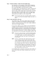
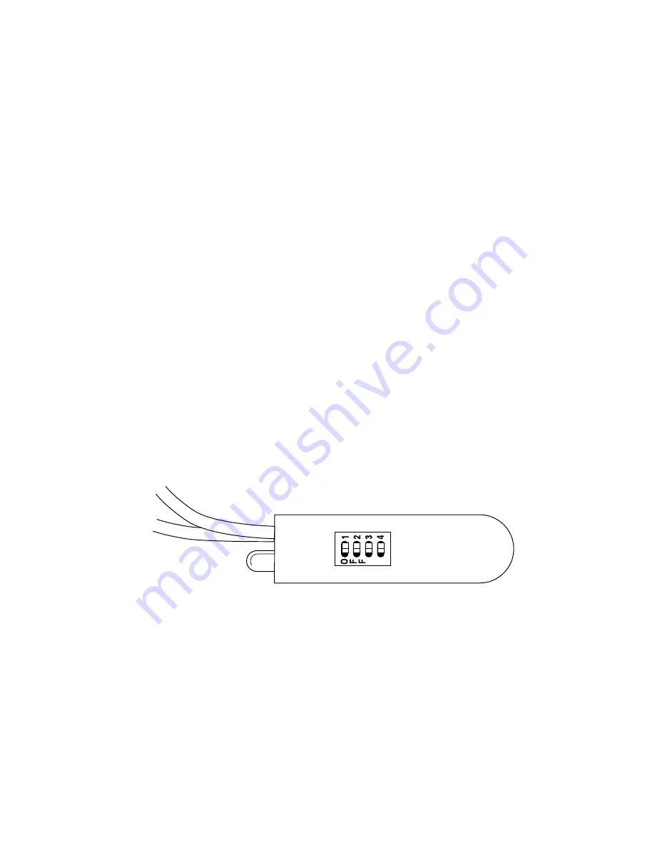
Step 5: Choose the Correct Dip Switch Settings
Because not all VSS signals are the same, you may need to
change the default dip switch setting on the VSS in-line cir-
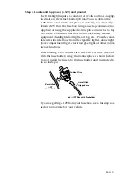
cuit. As a technical note, the switches have following func-
tions. Switch 1 is required if your VSS signal is a square wave
which does not go to ground. Switch 2 AC couples the signal
in and is used for sine wave VSS signals. Switch 3 improves
the sensitivity of the AC coupled signals. Switch 4 turns on
the LED test circuit.
NOTE:
No dip switch settings are required for the Ford F-250 truck har-
ness cable supplied with DriveRight Trip500AL VSS #8155VF
and DriveRight VSS Installation/Mounting Kit #8160VF. The
Ford F-250 cable is for use on F-250 trucks only. Do not use the
F-250 cable on other cars or trucks unless instructed to do so by
Davis Instruments.


