background image

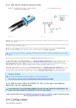
Step 1: After supplying power the Co-ordinator via M12 connector, the Node ID must be registered within the first 5

minutes, up to 40 WS.

Step 2: Bring the wireless sensor closer to the Co-ordinator's antenna then take off the wireless sensor battery, wait

for 5s then insert the battery again. If:

Buzzer plays 1 peep sound, LED blink 1 time, that means registering Node ID on Co-ordinator successfully.

Buzzer plays 2 peep sounds, LED blink 2 times, that this Node ID is already registered.

Node id added in this way will be written to the smallest node_id_n address which is = 0.

Set Rssi_threshold (see RF MODE CONFIG (in the 

Modbus Memmap of WS433-CL

), default -25): The case if Co-

ordinator is on high position and need to add node sensor. We set the sensor as close as possible and set the

Rssi_threshold to -80-90 or -100 to increase the sensitivity to allow WS433-CL-04 can add sensors at a longer

distance. After that, perform 2 steps of adding sensors and then reset Rssi_threshold = -25.

Enb_auto_add_sensors configuration (see RF MODE CONFIG (in the 

Modbus Memmap of WS433-CL

)): In case

you do not want to turn off the power WS433-CL, you can set Enb_auto_add_sensors = 1, this way we have 5

minutes to add nodes (add up to 40 nodes) . After 5 minutes Enb_auto_add_sensors will automatically = 0.

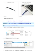
http://www.daviteq.com/en/manuals/books/long-range-wireless-co-ordinator-ws433-cl/page/user-guide-

for-long-range-wireless-co-ordinator-ws433-cl

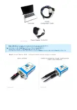
First, you need to prepare

6.3.1 Add Sensor Node ID automatically

If you do not hear the "Peep" sound, please disconnect the power the co-ordinator, wait a few minute and try

again.

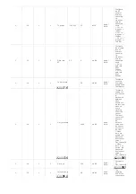
Memmap resgisters

You can download Modbus Memmap of WS433-CL with the following link:

https://filerun.daviteq.com/wl/?id=BKEaUzdArkoc0Hc7nfpRShdPVToVrqQZ 

6.3.2 Add sensor node into WS433-CL-04 (1) through intermediate
WS433-CL-04 (2) and Modbus

In case the sensor need to be added to WS433-CL-04 (1) has been installed in a high position, the

sensor cannot be brought close to WS433-CL-04 (1). For more details:

6.4 Configuration

Summary of Contents for WS433-LPC

Page 1: ...s installed properly Follow every steps Add sensors node to Co ordinator WS433 CL or with iConnector integrated Co ordinator Refer to section 6 3 for details Step 3 Installation Make sure compliance with manufacturer s recommendations Make sure the correct measuring range Refer to section 6 and section 7 for details Step 4 Check measurement results Check the reliability of the measurement compared...

Page 2: ...ike data sending interval health check cycle remotely from Globiots platform or via ModbusRTU software thru the WS433 CL Its default data rate is 50 kbps can be switched to 625 bps to increase the communication range The sensor can last up to 5 years with type AA battery Typical Applications People counter for public toilet People counter for Store shop SENSOR SPECIFICATION Sensor technology Lidar...

Page 3: ...m Type Approval Certification QCVN 73 2013 BTTTT QCVN 96 2015 BTTTT DAVITEQ B00122019 Security Standard AES 128 Operating temperature of PCB 40oC 60oC with Lithium Ultimate AA battery Housing Protection Self extinguisher ABS Dust and vapor protection Mounting Ceiling mount Dimension H120xW80xD45 Net weight 150 grams 1 Wireless sensor 2 Screws 4 Dimensions 5 Scope of delivery ...

Page 4: ... FoV as long as the distance measured by the sensor under this FoV is between 0 and a threshold value specified in mm From a timing perspective the sensor alternatively ranges on each of the two zones for a very short period of time in milliseconds It is possible to determine in which direction a person crosses the area depending in which order this person has been detected in the two zones as sho...

Page 5: ...direction or the other as described in Figure 4 List of status values The algorithm validates a crossing event only when a person has fully crossed the two zones It does not validate the event when the person remains for a long time under the FoV or when the person decides to return from the place he came from This is illustrated in the figure below the algorithm stops and the list of states is re...

Page 6: ...oor The distance between the sensor and the floor is 2345 mm and as the minimum distance measured by the sensor is 2290 mm the threshold is thus less than 2290 mm Note This calibration should be performed in the worst ambient light conditions to maximize the jitter and obtain a threshold that is relevant to all possible ambient lighting conditions the counting setup is exposed to Hi Byte is error ...

Page 7: ...at perform 2 steps of adding sensors and then reset Rssi_threshold 25 Enb_auto_add_sensors configuration see RF MODE CONFIG in the Modbus Memmap of WS433 CL In case you do not want to turn off the power WS433 CL you can set Enb_auto_add_sensors 1 this way we have 5 minutes to add nodes add up to 40 nodes After 5 minutes Enb_auto_add_sensors will automatically 0 http www daviteq com en manuals book...

Page 8: ...mber of nodes managed by WS433 CL Every time a node is added the Num of Node willincrease by 1 Every time a node is deleted the Num of Node isreduced by 1 Writing Num of Node 0 will delete all 40 node ids to 0 If you want to delete a node id then write it 0 with theWrite function is 16 and the Read function is 3 ...

Page 9: ...ile and run file application Daviteq Modbus Configuration Tool Version Choose COM Port the Port which is USB cable plugged in Set the BaudRate 9600 Parity none Click Connect untill the Status displays disconnected to connected It means the WS433 CL 04 is Template File https filerun daviteq com wl id xYEknMN8AhRLTmf73fXh9SWf0Ryp1QMa How to use the Modbus configuration software ...

Page 10: ...anation 4 1 2 Battery of sensor Node 10 30 60 99 uint16 Read Battery level only 04 levels 10 30 60 and 99 full When 10 Need to replace the battery 4 1 2 NRC_People_In uint16 Read Non resettable counter 4 1 2 NRC_People_Out uint16 Read Non resettable counter 4 1 2 Status bytes of sensor Node uint16 Read Hi Byte is error code Lo Byte is sensor type 4 1 2 RC_People_In uint16 Read Reset to 0 after sen...

Page 11: ...ta to co ordinator if the new measured value was changed more than the Delta value of the last measured value Default Cycle_wakeup is 120 seconds 3 16 1 2 Cycle_healthsta 60 7200 s 600 uint16 Read Write Every time interval of Cycle_healthsta sensor node will absolutely send data to co ordinator regardless any condition 3 16 2 4 Co ordinator id 0 uint32 Read Write Configure the ID number of Co ordi...

Page 12: ...ite Threshold count on how many people send Coordinator 3 16 1 2 Dist_threshold 1600 uint16 Read Write Threshold setting for laser sensor to distinguish between when people are present and when no one is standing under the sensor The laser sensor will measure the distance value from the sensor ceiling to the floor When there are people the measured laser sensor value Dist_threshold When there is n...

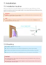
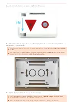
Page 13: ...ial NOTE Integrated WS433 CL iConnector Coordinator The coordinator must be placed at least4 meters above the ground and the WS433 LPC clearly visible 7 2 Mounting Installation method Mount to the ceiling Locate the mounting position at the entrance where people pass by and out of direct sunlight The direction of the triangle is the direction of counting people entering as specified in the payload...

Page 14: ... are included to be used to attach the sensor to surfaces such as Wood composite plastic If the ceiling surface is made of plaster it is recommended to use a specialinsert so that the device can firmly adhere to the ceiling surface Avoid dropping the device Fit the main body to the bottom cover in the correct direction the2 reed joints on the bottom cover should fit into the main body on the side ...

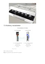
Page 15: ...Steps for battery installation Step 1 Using flat head screws to push into 2 reed joints 7 3 Battery installation ...

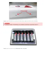
Page 16: ...hen insert 06 x AA 1 5VDC battery please take note the poles of the battery Step 3 Insert the top plastic housing Please note the 2 reed joint ATTENTION REVERSED POLARITY OF BATTERIES IN 10 SECONDS CAN DAMAGE THE SENSOR CIRCUIT ...

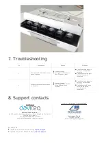
Page 17: ...ect Check that the battery is empty or not installed correctly Reconfigure the RF data rate with the button according to the instructions Manufacturer Daviteq Technologies Inc No 11 Street 2G Nam Hung Vuong Res An Lac Ward Binh Tan Dist Ho Chi Minh City Vietnam Tel 84 28 6268 2523 4 ext 122 Email info daviteq com www daviteq com Distributor in Australia and New Zealand Templogger Pty Ltd Tel 1800 ...

Reviews: