background image


3 INSTALLATION

 
3.1 Installation 

Installation of the device must be done 
concerning installation distance determined 
inside user manual.  
  
 
- While installs the device; obey installation 
distances determined above for making necessary 
interferences easily in the future.      
 
The installation surface of the device must be 
durable for carrying weight of device with water.  
 
Do not keep materials having risk such as 
inflammable, explosive at the same place with 
the device. 
  
 
In case of device installation wall is made of low 
heat durable material (wood, etc), wall isolation 
must be made suitable.


3.2 Plumbing 

Plumbing water hardness scale must not be 
higher than 20F. In case of higher hardness scale 
must be reduced. Damages that occur because of 
hardness scale will make device out of warranty. 
 
Condensing outlet of boiler is located lower left 
corner of the boiler. Condensing siphon must be 
absolutely filled water before operation of the 
boiler.  Otherwise, exhaust gas that is formed 
while combustion will leak to environment. 


-  Condensing outlet must be connected to 
discharge line. Metal material must not be used 
for discharge line. It must completely make of 
from plastic materials.  It can be followed by eye 
that water inside the condensing line flows from 
discharge. Any blockage inside condensing line 
causes breakdown by failure of boiler. Do not 
forget that this condition will be evaluated as out 
of warranty. 
 
Be sure that plumbing is completely cleaned 
before making plumbing connections.  
 
Installing valve to heating inlet and outlet of 
boiler will provide convenience for processes that 
will be made in the future.  


Your boiler’s operation pressure can be set max 
6 bars. Be sure that plumbing pressure is at the 
necessary range before operation. 


Internal circulation pump is located inside 
boiler. 


- In case of plumbing pressure is higher, it is 
needed to put hydraulic separator between 
plumbing and boiler.    
 
It must be expansion tank on the plumbing that 
is chosen suitable to line. It must have automatic 
air relief cock on the hydraulic separator and 
discharge valve at bottom of hydraulic separator. 


3.3 NATURAL GAS LINE 
Your device is compatible with NG and LPG 
operation.  At the product label it is written 
about which gas it is needed to operate. Control 
the correction of the gas type. 
 
Be sure that gas line pressure is at allowable 
range.
   
 
Be sure that gas pressure coming from plumbing 
is at allowable range. In case of it is high, you 
need to use pressure reduce regulator for 
plumbing.      
 
- There must be 1 pcs filter on the line for 
protecting from dirt that may be come from line.  
 
Before first operation of the boiler, air of the 
line must absolutely be taken. 

Summary of Contents for Navidens 50

Page 1: ......

Page 2: ...AXOM boilers provide following sufficiency Gas Appliances Directive 2009 142 EEC Boiler Efficiency Directive 92 42 ECC Electromagnetic Compability Directive 2004 108 CE Low Voltage Directive 2006 95 C...

Page 3: ...3 1 Installation 12 3 2 Plumbing 12 3 3 Natural Gas Line 12 3 4 Electrical Installation 13 3 5 Pipe Line 13 4 SAMPLE INSTALLATION DIAGRAMS 15 4 1 Heating System with Boiler 15 4 2 Cascade Heating Sys...

Page 4: ...tric supply and gas inlet of the boiler If there is freezing risk at water installation or boiler system you need to discharge water inside the plumbing Control the operation of the air conditioner of...

Page 5: ...the device significant points that must be careful before operation of the system or during operation of system importance of periodic maintenance in terms of performance and efficiency of device and...

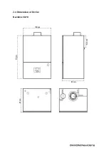
Page 6: ...2 4 Dimension of Device Navidens 50 70...

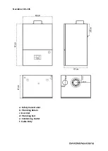
Page 7: ...Navidens 125 145 a Safety Valve Outlet b Plumbing Return c Gas Inlet d Plumbing Exit e Condensing Outlet f Cable Entry...

Page 8: ...2 5 Boiler Installation Distances...

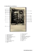
Page 9: ...zation Electrode 6 Ignition Electrode 7 Sight Glass 8 Combustion Space 9 Pipe Gas Temperature Sensor 10 Condensation Tank 11 Siphon 12 Electronic Control Card 13 Circulation Pump 14 Safety Valve 15 Re...

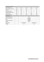
Page 10: ...Partial Load 30 C 108 107 106 85 106 08 Nominal Heat Load 80 60 C 97 97 96 12 95 94 Min Heat Load 80 60 C 95 96 94 95 Efficiency Class Pipe Dates Pipe Pressure Pa 150 135 240 210 Exhaust Gas Flow Rate...

Page 11: ...e inch 3 4 3 4 1 1 Condensing Outlet mm 30 30 30 30 Safety Discharge Outlet mm 30 30 30 30 Fresh Air Inlet mm 125 125 150 150 Exhaust Gas Outlet mm 80 80 100 100 Specifications Cascade Connections 256...

Page 12: ...ing line flows from discharge Any blockage inside condensing line causes breakdown by failure of boiler Do not forget that this condition will be evaluated as out of warranty Be sure that plumbing is...

Page 13: ...rrespond with 2 meter pipe and 45 bend correspond with 1 5m pipe Do not forget that extra connection accessories that will be used for line will also create resistance and will reduce allowed total pi...

Page 14: ...Concentric Pipe System Double Pipe System...

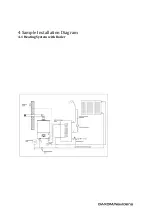
Page 15: ...4 Sample Installation Diagram 4 1 Heating System with Boiler...

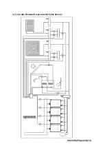
Page 16: ...4 2 Cascade Heating Diagram with Solar Energy...

Page 17: ...stance between them C33 Vertical exit is made from roof by interwoven pipes C43 Connection to common pipe outlet by interwoven pipes C53 Exit from wall or roof with separate pipes outlets at areas tha...

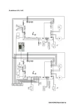
Page 18: ...6 ELECTRIC PROJECT Navidens 50 70...

Page 19: ...Navidens 125 145...

Page 20: ...Pressure Switch CS Pipe Gas Sensor TL Safety Thermostat M Fan Motor P Circulation Pump CLEMENS DESCRIPTION QX2 Boiler Cycle Pump QX3 Heating Cycle Pump H5 Room Thermostat B9 Outside Environment Senso...

Page 21: ...7 ACESSORIES PRODUCT DESCRIPTION PHOTO Cascade Communication Module Three Way Valve Connection Module Outlet Air Sensor Room Thermostat Cascade Sensor...

Page 22: ...100 150 mm 45 90 Degree Bends 80 125 mm 100 125 mm Exhaust Gas Pipe 80 mm 100 mm Additional Pipe 80 125 mm 100 125 mm Fresh Air Inlet Accessory 80mm 100mm For double pipes system Exhaust Gas Outlet A...

Page 23: ...reen by ESC button after you chose AUTO your device will start to operate according to set operation hour 8 3 Room Temperature Setting While the device is in home screen turn the number 8 button Tempe...

Page 24: ...sensitively By opening hot bulb seal between burner and heat exchanger must be controlled and if it is needed it must be changed Ignition and ionization electrodes must be cleaned by emery If it is n...

Page 25: ...ceeded 6 5 Heating cycle water pressure is too low 9 Bottom water pressure limit is reduced under1 10 Change battery of outside air sensor 6 18 Heating cycle water pressure 2 is too low 9 Bottom water...

Reviews: