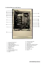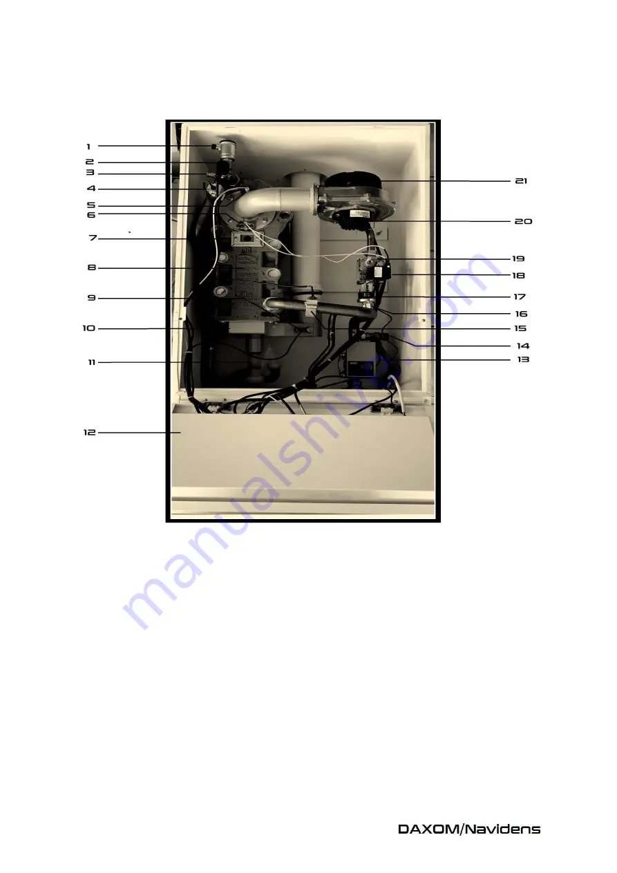
2.6 Inside Structure of the Device
1-
Automatic Air Relief Cock
2-
Safety Thermostat
3-
Manual Air Relief Cock
4-
Outlet Water Temperature Sensor
5-
Ionization Electrode
6-
Ignition Electrode
7-
Sight Glass
8-
Combustion Space
9-
Pipe Gas Temperature Sensor
10-
Condensation Tank
11-
Siphon
12-
Electronic Control Card
13-
Circulation Pump
14-
Safety Valve
15-
Return Water Temperature Sensor
16-
Manometer Hour Connection
17-
Pressure Switch
18-
Pulse Ignition System
19-
Gas Valve
20-
Air Suction Inlet
21-
Air Fan
Summary of Contents for Navidens 50
Page 1: ......
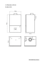
Page 6: ...2 4 Dimension of Device Navidens 50 70...
Page 8: ...2 5 Boiler Installation Distances...
Page 14: ...Concentric Pipe System Double Pipe System...
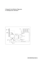
Page 15: ...4 Sample Installation Diagram 4 1 Heating System with Boiler...
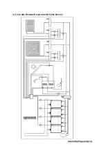
Page 16: ...4 2 Cascade Heating Diagram with Solar Energy...
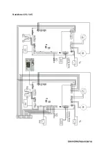
Page 18: ...6 ELECTRIC PROJECT Navidens 50 70...
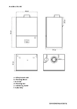
Page 19: ...Navidens 125 145...


