background image

32

5.  TERMS OF WARRANTY

If equipment failure occurs in the normal course of service having been competently  
installed  and when operating within its specified duty limits warranty will be provided as 
follows:-

Ÿ


Up to 6 months - The item will be replaced or repaired at no charge.

Ÿ

Over 6 months, less than one year - The item will be replaced or 
repaired at a cost to the customer of 50% of the Davis & Shirtliff 
market price.

The  warranty  on  equipment  supplied  or  installed  by  others  is  conditional  upon  the 
defective  unit 

being  promptly  returned  free  to  a  Dayliff  retailer

  and  collected 

thereafter when repaired. No element of site repair is included in the warranty and any site 
attendance  costs  will  be  payable  in  full  at  standard  charegeout  rates.  Also  proof  of 
purchase including the purchase invoice must be provided for a warranty claim to be 
considered.

Ÿ

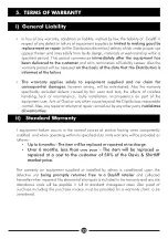
In lieu of any warranty, condition or liability implied by law, the liability of   Dayliff in  
respect of any defect or failure of equipment supplied

 is limited to making good by 

replacement or repair 

(at the Distributors discretion) defects which under proper use 

appear therein and arise solely from faulty design, materials or workmanship within a 
specified period. This period commences 

immediately after the equipment has 

been delivered to the customer

 and at its termination all liability ceases. Also the 

warranty period will be assessed 

on the basis of the date that the Distributors is 

informed of the failure

.

Ÿ

The  warranty  applies  solely  to  equipment  supplied  and  no  claim  for 
consequential damages

,  however  arising,  will  be  entertained.  Also  the  warranty 

specifically  excluded  defects  caused  by  fair  wear  and  tear,  the  effects  of  careless 
handling,  lack  of  maintenance,  faulty  installation,  incompetence  on  part  of  the 
equipment user, Acts of God or any other cause beyond the Distributors reasonable 
control. Also, any repair or attempt at repair carried out by any other party 

invalidates 

all warranties.

i)  General Liability 

ii)   Standard Warranty


Summary of Contents for B25

Page 1: ...TRIMMERS Installation Operating Manual Shamba Tool M32 B25...

Page 2: ......

Page 3: ...SPECIFICATIONS 1 1 2 SYMBOLS WARNINGS 4 OPERATION 3 6 TROUBLE SHOOTING 4 29 INDEX Davis Shirtliff Ltd 2023 Contents herein are not warranted WARRANTY 5 32...

Page 4: ...M32 Multi tool system featuring three distinct head options for grass trimming hedge trimming and pole pruning These attachements are easily interchangeable attaching seamlessly to the handle body whi...

Page 5: ...Assembly 3 Handle Assy 4 Harness Assy 5 Ignition Switch 6 Safety Lever 7 Fuel Tank Lid 8 Purge Bulb 9 Fuel Tank 10 Throttle Trigger 11 Air Cleaner Cover 12 Choke Cold Starts 13 Starter Handle 14 Debri...

Page 6: ...n Switch 6 Throttle Trigger Lockout or Safety Lever 7 Throttle Lever 8 Throttle Cable 9 Air Cleaner 10 Fuel Tank 11 Starter Knob 12 Cutting Line Head 13 Gear Case 14 Debris Guard 15 Blade optional 16...

Page 7: ...o not mix fuel in an enclosed room or near open ames Assure adequate ventilation WARNING Always mix and store the fuel in a properly marked container that is approved by local codes and ordinances for...

Page 8: ...use this unit for any job other than that for which it is intended as described in this manual WARNING Do not overreach Keep proper footing and balance at all times Do not run the unit while standing...

Page 9: ...gine and t the casing over the cutting attachment before transporting the trimmer over long distances When transporting it in a vehicle properly secure it to prevent turnover fuel spillage and damage...

Page 10: ...stall locking tool Thread cutter head onto shaft turning it clockwise until it is tight Remove locking tool Refer to pg 12 for additional information Install handle and lower cap on the rubber cover a...

Page 11: ...w 4 must not stick out when tightened Pull out the stop pin 1 and push the rod 2 right down until the stop pin 1 clicks into the hole 3 in the rod as shown in picture 2 This is easily done by rotating...

Page 12: ...situated at the outside 5 To quickly detach the grass trimmer from the harness pull the quick release latch tab upward 6 Insert the latch tongue in the slot of the quick release latch to reattach the...

Page 13: ...or the work or add fresh fill of 2 stroke fuel as above It is recommended that the 2 stroke is mixed in a separate container before filling into the fuel tank WARNING WARNING Store fuel only in a clea...

Page 14: ...ward towards the operator If the line head is held at to the ground so that cutting occurs on the whole line circle debris will be thrown at the operator WARNING WARNING Use only quality nylon mono la...

Page 15: ...slowly SCALPING AND EDGING Both of these are done with the line head tilted at a steep angle Scalping is removing top growth leaving the earth bear Edging is trimming the grass back where it has spre...

Page 16: ...13 NYLON ROPE REPLACEMENT 1 2 3 4 1 2 2x2 1m 82 7in 3 120mm 4 75 in 2 5mm 5 4 6 7...

Page 17: ...om the body as possible VERTICAL TRIMMING HEDGING HEAD Before starting work check the following All the screws on the machine and the blade are tightly fastened Blades are sharp and there are no signs...

Page 18: ...If the cutting device gets excessively hot during operations grease the blade s internal surfaces with the correct oil LUBRICATING THE BLADES DURING JOBS WARNING This operation must only be performed...

Page 19: ...together WARNING Any intervention on the blade should always be conducted at a specialised Centre that has the most appropriate tools and is able to perform the operations without compromising the sa...

Page 20: ...locked by the branch move over the saw and then saw the branch over again Cross Cut To avoid pinching the bar in the cut position the cutting attachment with the hook against the branch and then perfo...

Page 21: ...counterclockwise until the tensioner slide butts against the left end of the housing slot then back it off 5 full turns Removing the Chain Sprocket Cover WARNING Guide bar and chain adjustments can on...

Page 22: ...bar by hand Fitting The Chain Adjusting the Throttle Cable A properly adjusted throttle cable is the precondition for correct operation in the full throttle starting throttle and idle positions Adjus...

Page 23: ...brication clean the oilways Checking Chain Lubrication The saw chain must always throw off a small amount of oil Never operate your saw without chain lubrication If the chain runs dry the whole cuttin...

Page 24: ...d with fuel Starting Method 1 Remove the blade scabbard Check that the chain is not touching the ground or any other obstacles Place the unit on the ground It must rest securely on the engine support...

Page 25: ...o disengage the starting throttle position The slide switch moves to the normal run position and the engine settles down to idle speed Open the throttle slightly Warm up the engine for a short period...

Page 26: ...gine heat can be dissipated by the flow of cooling air This protects engine mounted components ignition carburetor from thermal overload WARNING The chain contracts as it cools down If it is not slack...

Page 27: ...feed pressure Do not work with a dull or damaged chain as it will increase the physical effort required produce unsatisfactory results and a higher rate of wear Clean the chain Check the chain for cr...

Page 28: ...is an increased risk of kickback with resulting risk of injury ENGINE MANAGEMENT Cleaning the Air Filter Accumulated dust in the air filter will reduce engine efficiency increase fuel consumption and...

Page 29: ...ispose of fuel properly in accordance with local environmental requirements Run the engine until the carburetor is dry this helps prevent the carburetor diaphragms sticking together Remove the saw cha...

Page 30: ...engine or abnormalities in engine performance When filter is dirty replace the filter When the inside of the fuel tank is dirty it can be cleaned by rinsing the tank out with gasoline CHECK SPARK PLU...

Page 31: ...onths If Problem If Damaged If Required Control Handle Check Operation Air Filter Pickup body in fuel tank Fuel Tank Clean Carburetor Spark Plug Cooling Inlets All accessible screws and nuts not adjus...

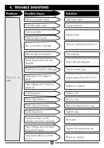
Page 32: ...ily deposits Clean the oily deposits Spark plug insulation damage Replace spark plug Spark gap is too large or small Adjust spark plug 0 6 0 7mm High voltage wire breach or break off Replace or tighte...

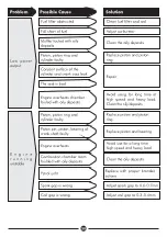
Page 33: ...led with oily deposits Avoid using for long time at high speed and heavy load Clean the oily deposits E n g i n e r u n n i n g unstable Piston piston ring and cylinder faulty Replace piston and pisto...

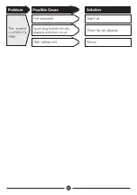
Page 34: ...31 Problem Possible Cause Solution The engine s u d d e n l y stops Fuel exhausted Add Fuel Spark plug fouled with oily deposits and short circuit Clean the oily deposits High voltage wire Rewire...

Page 35: ...implied by law the liability of Dayliff in respect of any defect or failure of equipment supplied is limited to making good by replacement or repair at the Distributors discretion defects which under...

Page 36: ...INS540A 12 23...

Reviews: