4
2. INSTALLATION
2.1 Equipment Specication
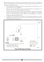
The Ultrafiltration plant consists of the following major components
1. Feed pump/Backwash/CIP pump.
2. Electric Solenoid valves -Inlet, Flush and Drain valves.
3. Backwash/CIP tank.
4. Pump controller.
5. Timer circuit.
6. UF membrane.
7. Piping.
8. Optional Waste water tank.
9. Optional Raw water tank.
10.
Optional chemical dosing tanks.
11.
Optional chemical dosing systems.
2.2 Module Description
Systems are frame mounted and supplied as complete units with all necessary accessories
and controls for simple integration with the flow process. They offer the following
features:-
Ÿ
Fully automated plant operation including normal filtration and flushing cycle.
Ÿ
High efficiency single Dayliff feed/backwash/Cleaning pump saving energy, i.e.
Low CAPEX and OPEX.
Ÿ
Integrated automated backwash/flushing/cleaning process.
Ÿ
System monitoring instruments including product flow meter and pressure gauges.
Ÿ
120-micron pre-filter.
Ÿ
Skid mounted for simple installation.
Ÿ
Integrated CIP/Cleaning/Backwash/Flushing tank.
Ÿ
Dry running pump protection
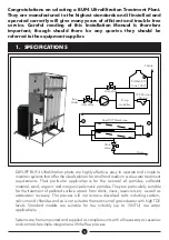
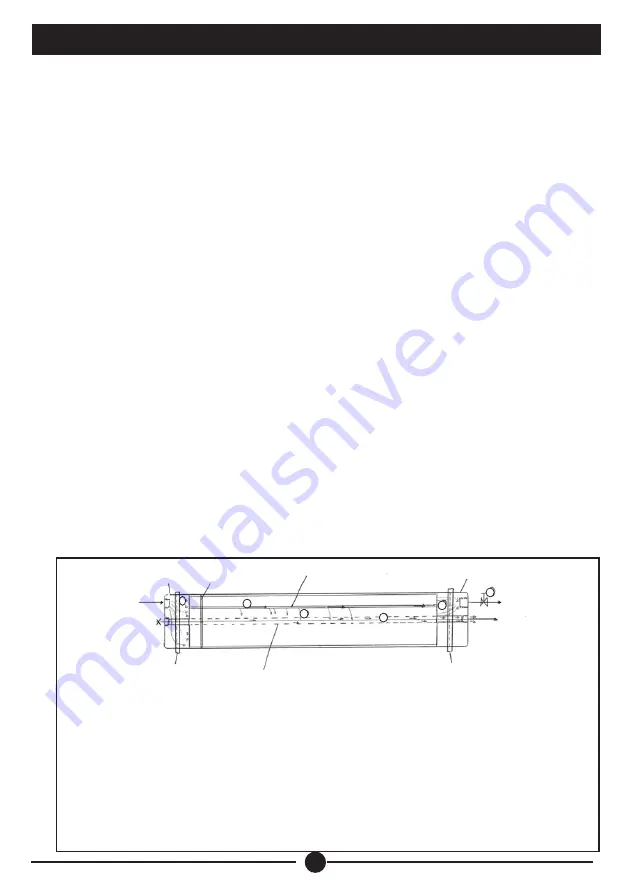
Fig 2: UF Membrane Cross Section
1. Feed water enters chamber on offset
2. Floods hollow fibres internally
3. Breaks through walls
4. Exits through middle (center tub) pipe
5. Flows through center fitting
6. Electric valve flush valve opened to strip build up inside each hollow fibre
1
2
3
4
5
6
Centre tube
with holes in
Clamp
Clamp
Seal
Product
(Clean)
Flush
End Cap
End Cap
Raw
Feed
Hollow Fibre
Magnied
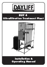
Summary of Contents for BUF 4
Page 1: ...Installation Operating Manual BUF 4 Ultrafiltration Treatment Plant...
Page 2: ......
Page 14: ......
Page 19: ......
Page 20: ......

