background image

5

3.2 Electrical Connections

WARNING

Electrical  work  to  be  carried  out  by  competent 
qualified and licenced electrician in strict conformity 
to ruling national conditions and local regulations. All 
wiring  and  external  switchgear  to  comply  with  the 
ruling local regulations in accordance with the latest 
edition of IEE wiring regulations.

Ÿ

 For the pump fuse protection use a 3 Amp fuse.

Ÿ

 A means of disconnection from the power supply having a contact separation 
of at least 3mm in all poles must be provided.

Ÿ

 If the pump already has a cable fitted to it, ensure the pump is isolated from 
the mains before removing the terminal cover.

3.3 Wiring Procedures

2

1.  Use  heat  resistant  3x0.75mm   core  cable  with  rubber  insulation  rated  at 

0

110 C minimum.

2. Cut the cable to required length.
3. Remove the terminal cover.
4. Thread cable through grommet.

WARNING

The pump must be sufficiently earthed, else personal injury 
may occur.

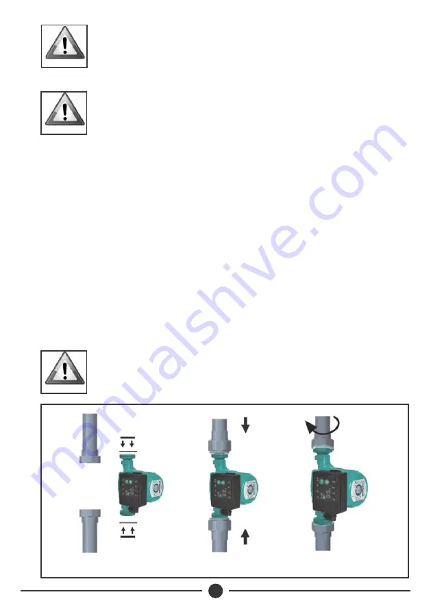
Step 1

Step 2

Step 3

NOTE

After  use,  the  Manual  Restart  knob,  should  be 
screwed back tightly into its original position.

Summary of Contents for DQA

Page 1: ...DQA Circulator Pumps Installation Operating Manual...

Page 2: ......

Page 3: ...PUMP SPECIFICATIONS 1 1 3 INSTALLATION 4 OPERATION 4 7 TROUBLE SHOOTING 6 10 INDEX Davis Shirtliff Ltd 2020 Contents herein are not warranted TERMS OF WARRANTY 7 11 MAINTENANCE 5 10 2 WARNINGS 3...

Page 4: ...adjusted according to system demand and constant pressure where pressure remains constant irrespective of system demand Three selectable speeds so the pump performance can be matched to system require...

Page 5: ...ATING CONDITIONS Pumped Liquid Thin clean chemically non aggressive liquids without solid particles or fibres 0 0 Liquid Temperature 10 C to 110 C 0 Max Ambient Temperature 10 50 C Max Operating Press...

Page 6: ...led in either a high point in the system where air can collect or a low point where sediments could build up WARNING Pipes on both sides of the pump should be supported to reduce strain and must be co...

Page 7: ...or a long time WARNING Dry running will void warranty WARNING The pump should be stored in a cool dry and well ventilated place 3 INSTALLATION 3 1 Electrical Connection If the electrical connection bl...

Page 8: ...e power supply having a contact separation of at least 3mm in all poles must be provided If the pump already has a cable fitted to it ensure the pump is isolated from the mains before removing the ter...

Page 9: ...prevent water leakage The location of terminal box can be adjusted accordingly to users request To achieve this Isolate power supply Watch out for high water temperature Close the valves at inlet and...

Page 10: ...Pressure Curve Max Proportional Pressure Curve Night Mode LED Display Power Auto Adaptation Speed I III A PPI CPII CPI Speed II Speed III Night Operation is effected by pressing button The pump will r...

Page 11: ...se CPI Min constant pressure curve According to the flow rate of system demand the pump working point changes on the basis of min constant pressure curve The constant pressure of pump is irrelevant wi...

Page 12: ...k that the shaft rotates freely and that the knob can be seen rotating on initial start of the pump Venting Bleeding When the system is filled with water the pump will normally self vent air within a...

Page 13: ...ator adjustment should only be made with electrical supply switched off 6 TROUBLE SHOOTING PROBLEM Pump fails to start Pump start but provides incorrect circulation Noise SOLUTION Check power supply f...

Page 14: ...Davis Shirtliff hereafter called the Company in respect of any defect or failure of equipment supplied is limited to making good by replacement or repair at the Company s discretion defects which und...

Page 15: ......

Page 16: ...INS449A 02 20 www davisandshirtliff com...

Reviews: