background image


7

M2A-FM User Manual 

M2A-FM has been set at the factory to operate at 120VAC unless otherwise specified on the shipping 
carton. The M2A-FM export version is configured for 240VAC operation. 

Please connect your M2A-FM to 

an uninterruptible power supply (UPS) to protect against power surges and brownouts.   


Antenna Input Connections.  

75ohm F-type connector is provided on the M2A-FM rear panel for an FM 

antenna. Rear panel switch selects for antenna or high-level sample port inputs (7VP-P max).


Audio Output Connections.  

Analog audio left and right outputs are on rear-panel XLR connectors with pin 

1 GND, pin 2 + and pin 3 -.  The digital audio output is transformer-isolated in S/PDIF format on a rear-panel 
XLR connector with pin 1 GND, pin 2 XFMR and pin 3 XFMR.   The M2A-FM digital audio output is 5.1 
surround capable. 


M2A-FM Operating Description - Controls and Indicators


Power-up and Standby

.  The Power switch is located on the rear panel of the M2A-FM; when switched on 

the hardware and software version of your M2A-FM will be displayed for 3 seconds on the M2A’s VFD.     
 
In any mode, if the SELECT and DN


switches are depressed simultaneously for 5 seconds, monitor goes 

into Standby mode with all front panel controls and indicators blanked except for SELECT and UP switches; 
the M2A’s VFD then indicates the “DaySequerra Standby” message.  Holding SELECT together with UP 
switch in for 5 seconds when in this Standby mode reactivates all front panel controls and indicators and 
returns monitor to normal operation.  
 

TUNER BAND 

– The front panel TUNER BAND switch selects manual FM tuning controlled by UP and DN 

controls.  Holding switch in for 5 seconds forces monitor into Forced Mono mode; MONO is displayed on 2

nd


line of VFD. Blue arrow LED illuminates when mode is active.  Holding on startup allows you to select 
between 100kHz and 200kHz tuning and 75 and 50 uS de-emphasis. 
 

PRESETS

 – The M2A-FM has capability to recall 20 preset or stored FM stations using the front panel 

PRESETS switch. Blue arrow LED illuminates when monitor is in PRESETS mode.  UP and DN controls 
scroll through stored stations.  Preset stations are stored for recall in positions F1 through F20. PRESETS 
Arrow LED illuminates when monitor is in PRESETS tuning mode.   
 
When the M2A-FM has acquired any station in TUNER BAND mode and the SELECT switch is held for 5 
seconds, monitor enters PRESETS store mode and PRESETS arrow LED flashes. UP and DN controls then 
allow user to scroll through F1 through F20.   When the desired preset location is indicated on VFD, next 
momentary push of SELECT switch stores selected station in that PRESETS position.  
 

UP 

and 

DN 

– For manual FM tuning in TUNER BAND mode and scrolling through PRESETS in PRESETS 

mode.  

 
SELECT 

– Multi-function switch for storing PRESETS and controlling other monitor functions, as described 

below. 

 
ALARM SET 

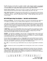
– Momentarily pressing the front panel ALARM SET switch activates the Alarm Configuration 

Menu. VFD displays ALARM CONFIG with “ENABLE” and “SETUP” options. Select desired option using UP 
and DN switches to toggle the setting. Select “ENABLE” to arm all alarms as configured and exit Alarm 
Configuration Menu; select “SETUP” to continue with alarm configuration menu. Exit the Alarm Configuration 
Menu at any time by pressing ALARM SET switch. 


    A L  A R M   C O N F  I  G    
  E N A B L E     > S E T U P < 

Summary of Contents for M2A-FM

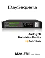
Page 1: ...M2A FM Analog FM Modulation Monitor User Manual Ready ...

Page 2: ...ck extensive listening field testing and careful refinement In the event that you encounter any technical or operational difficulties with this or any DaySequerra product please feel free to contact us at 856 719 9900 Our office hours are from 9 to 5 ET Monday through Friday Or you can email your questions to info daysequerra com Also please remember to visit our website www daysequerra com for wa...

Page 3: ...2011 All logos and trademark used herein are the property of their respective owners Specifications subject to change M2A FM Revision D M2A FM Features Brilliant accurate bargraph metering of analog programming Multi function vacuum florescent display VFD shows decoded RBDS Precision metering of FM Pilot and SCA injection levels MPX output lets you connect external SCA demodulators Six dry contact...

Page 4: ...re updates Introduction The DaySequerra M2A FM is the world s best analog FM monitor complete with world wide tuning and de emphasis settings The M2A FM measures your analog signal with digital accuracy insuring that readings will remain stable and reliable over time Selectable measurement integration times let you control peak reading for maximum modulation The M2A FM includes a sensitive yet sel...

Page 5: ...Key Features FM ANTENNA INPUT Industry standard 75 ohm F connector FM HIGH LEVEL INPUT Industry standard 50 ohm BNC connector 7VAC Pk Pk maximum ANTENNA HIGH LEVEL INPUT SELECT User selected for antenna or high level input STEREO ANALOG OUTPUTS Balanced 4dBm for 100 analog modulation DIGITAL AUDIO OUTPUT 110 ohm transformer isolated for all broadcasts IEC320 POWER INLET 120VAC with integrated fuse...

Page 6: ...any shipping damage If damage is found or suspected please notify the carrier at once and then contact your dealer The DaySequerra M2A FM is shipped in one carton which contains the M2A FM unit an AC power cable a TorxTM T 8 L key and this User Manual We strongly encourage you to save the shipping carton and shipping materials supplied with your M2A FM They are specially designed to properly prote...

Page 7: ...ch selects manual FM tuning controlled by UP and DN controls Holding switch in for 5 seconds forces monitor into Forced Mono mode MONO is displayed on 2nd line of VFD Blue arrow LED illuminates when mode is active Holding on startup allows you to select between 100kHz and 200kHz tuning and 75 and 50 uS de emphasis PRESETS The M2A FM has capability to recall 20 preset or stored FM stations using th...

Page 8: ...f Push SELECT to continue R F C A R R I E R L O S S S E T O F F If SET is selected submenu for Level threshold with LOW MED and HIGH options is displayed next LOW option sets RF carrier loss threshold for approximately 10µV 25dBf MED option sets RF carrier loss threshold for approximately 100µV 45dBf and HIGH option sets RF carrier loss threshold for approximately 3KµV 75dBf Use UP and DN switches...

Page 9: ...tches to toggle the setting and highlight the desired option Push SELECT switch to continue A U D I O L E V E L L O W M E D H I G H Submenu for Alarm Delay with 30 60 120 and 240 second options is displayed next Use UP and DN switches to toggle the setting and highlight the desired option A L A R M D E L A Y 3 0 6 0 1 2 0 2 4 0 S Push SELECT switch to save and increment the menu to the next alarm ...

Page 10: ...ration menu select OFF to set this alarm function to off Push SELECT to continue P I L O T P R E S E N T S E T O F F If SET is selected submenu for Alarm Delay with 30 60 120 and 240 second options is displayed next Use UP and DN switches to toggle the setting and highlight the desired option A L A R M D E L A Y 3 0 6 0 1 2 0 2 4 0 S Push SELECT switch to save and increment the menu to the next al...

Page 11: ...for Modulation Level is displayed next Use UP and DN switches to vary the setting between 100 125 Set the Modulation to the desired trigger level Push SELECT to continue M O D U L A T I O N L E V E L 1 0 5 If SET is selected submenu for Alarm Delay with 30 60 120 and 240 second options is displayed next Use UP and DN switches to toggle the setting and highlight the desired option A L A R M D E L A...

Page 12: ... e all front panel controls are inhibited except for PANEL LOCK switch analog and digital audio outputs continue VFD alternates between displaying FRONT PANEL LOCKED and normal display for tuned station Blue arrow LED illuminates only when switch is being pushed or when mode is active Holding PANEL LOCK switch for 5 seconds un blanks all front panel controls and indicators and returns M2A FM to no...

Page 13: ...dicates relative RF signal level received at the antenna connector on the M2A FM rear panel A minimum of 5 RF signal strength segments must be illuminated indicating 65dBf for accurate demodulation and carrier level measurements Headphones Recessed screwdriver control adjusts headphone output level on recessed TRS jack Default set at the factory is 7 0dBm 0 1VAC Pk Pk SCA and AM Measurements Overv...

Page 14: ...N switches can be used to select another subcarrier frequency to be measured or the Carrier Modulation Select switch can be used to exit the Sub Pilot injection level measurement mode If the UP and DN switches are used to select another subcarrier frequency to be measured in this case the 57kHz SCA the process is identical to that described above In this example the VFD now indicates the 57 kHz su...

Page 15: ... Peak Alarm 15 14 11 M2A FM Ethernet Port Option The M2A FM Ethernet Port Option offers DaySequerra s Remote Dashboard TM software a proprietary PC based application and an Ethernet interface to provide remote control monitoring for FM broadcasts as well as a robust alarm panel Please email your M2A FM serial number and contact information to support daysequerra com or register your unit on our we...

Page 16: ... customer accordingly DaySequerra reserves the right to replace any product that has been discontinued from its product line with a new product of comparable value and function This warranty shall be void in the event a covered product has been damaged or failure is caused by or attributable to acts of God abuse accident misuse improper or abnormal usage failure to follow instructions improper ins...

Reviews: