10
M4.2Si TimeLock User Manual
•
AC Power - Auto-sensing 85-264VAC, 47-63Hz input.
•
The Power (Rocker) switch is located on the rear panel of the M4.2 TimeLock™; when switched
on the unit model number will be displayed on the LCD.
LCD
4.
Figure 3.
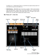
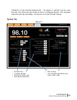
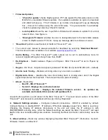
1. Tuner Frequency –
Selects manual AM and FM tuning with UP and DN controls
2. Station Call Letters –
Displays the station call letters with the Band
3. IP / PAD & RBDS Data –
Toggles between a static IP address and decoded RBDS from
analog broadcasts and PAD data from an HD RadioTM broadcasts for display on the bottom of
the LCD. This field also displays active alarm details, which override IP/PAD/RBDS data.
4. SNR Indicator –
Strength bars are displayed indicating the signal to noise ratio.
(
digital only)
5. BAND/PRESET –
AM and FM Bands are selected; 25 AM and FM including Multicast stations
are available to be stored.
6. ST/Multicast –
Displays the available multicast stations HD 1 thru HD 8. ST is displayed if HD
is not available
7. Forcing –
Switch between Forced Auto, Digital, Analog, and Mono. By default the tuner is set
to AUTO. In Forced AUTO mode, the tuner will receive an HD RadioTM digital broadcast if one
is being transmitted; if not, the tuner will receive the analog broadcast.
•
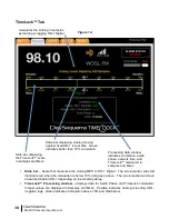
*When the Webserver TimeLock tab is selected the tuner will automatically enable
SPLIT mode. Exiting TimeLock will not disable SPLIT mode and should be manually
disabled if desired.
1.
2.
3.
5.
6.
7.


