17
Limiter Menu
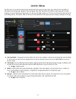
The limiter is a tool that will allow input signals below the given threshold to pass through the amplifier un-
affected but will attenuate signals if they are higher than the threshold. The limiter only responds to actual
clipping, and automatically compensates for load and voltage variations. This tool can be particularly useful for
protecting drivers. The limiter LED on the front of the device will illuminate when limiting is actively occurring.
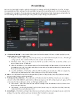
A. Channel Mode - Change which channel the limiter is to be applied. Link mode will apply the same limiting
to both, but you can also set individual limit for each channel (A and or B) if the APA1200DSP is used in
stereo mode.
B. Threshold – Set the threshold of the limiter. Signals below this threshold will pass through unaffected, but
signals above this threshold will be limited. 0dB effectively means the limiter is OFF.
1. Range: -99dB to 0dB
C. Attack – Determines how quickly limiting is applied to the input signal. A lower value means a faster at-
tack, and the limiter reacts quickly to a signal that has peaked above the threshold value.
1. Range: 1ms to 100ms
D. Release – Determines how quickly the limiter stops affecting the signal. The lower the value, the quicker
the limiter will stop reacting to a signal that peaked above the selected threshold.
1. Range:
90ms to 3000ms


