Fig.
2
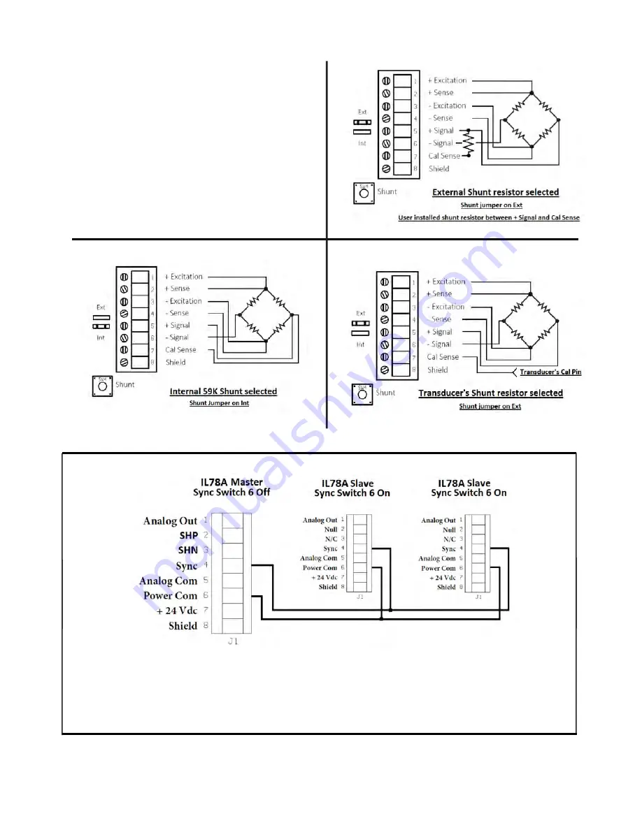
Master / Slave Wiring
When more than one IL78A is being used in the same measurment setup, beat frequencies can be produced by
the excitation clock oscillator. To prevent this, the user should declare one of the IL78A units as a Master via
switch 6 on the front panel. The other units should be switched to Slave and wired as shown with the SYC
terminals connected and a separate Power Common wire. If the units share a common power supply, the
Power com terminal should be connected at the modules.
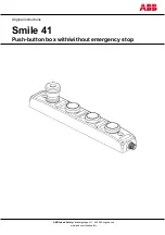
Shunt Resistor Selection
The IL78A has a Internal and External shunt
selection jumper located between the two wiring
connectors. Below are the appropriate wiring and
jumper selections depending on the application
using the recommended 7 wire configuration.
TRANSDUCER CONNECTIONS IL78A.2
AC Strain Gage Conditioner
Module
IL78A