6.
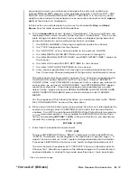
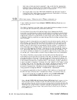
Before you define your “EXECUTE” function, you should first set up its
“trigger bit.” For this purpose you should select a currently unused bit
from among your system’s first 32 bits.*
7.
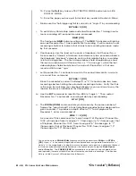
Enter a command of
LGT x = r [CR]
where “x” is again the number of the channel you calibrated in Section 10,
above, and “r” is the number of the selected trigger bit (it must be a num-
ber from 0 through 31).* As you learned in the previous section, this com-
mand automatically assigns a “logic source” of “NONLATCHING LIMIT
LOGIC” to Bit No. r.
8.
Now command
EXU r = PAGn:CHN900=0 [CR]
where “n” is the number of the video page that displays Channel No. 900.
The command string specified by an
EXU
command can take up to 31
ASCII characters, including spaces; individual commands are separated
by colons.
9.
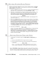
Increase the load applied to Channel No. x’s source transducer until it is
greater than the high-limit value you entered in Section 13, Step b, above.
10. As soon as Channel No. x’s high limit is violated, the video page contain-
ing Channel No. 900 should automatically appear, and the data field for
this channel should report a value of “0.”
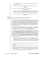
11. Now enter a command of
BIT 898 = 0 [CR]
12. Call to display the video page you composed in Section 13, Step i, above,
for the “live” display of Bit Nos. 898 and 899. Verify that the bit-state field
for Bit No. 898 reads “LOW.”
13. Keep the “high violation” load on the transducer, and enter a command of
EXU /r = DIR:CHN900=25:BIT898=1 [CR]
where “r” is again the number of the selected trigger bit. This command
instructs the system to
• call the Page Directory
• load Channel No. 900 with the number “25,” and
• set Logic Bit No. 898 to “Logic 1”
when Logic Bit No. r “goes low”—i.e., when the transition of Bit No. r from
“Logic 1” to “Logic 0” is perceived.
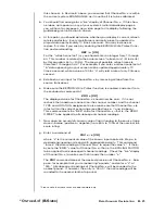
14. Remove the transducer load. The Page Directory should automatically
appear.
15. Call the video page containing Channel No. 900. That channel’s data field
should now read “25.”
B - 31
A
UTOMATIC
C
OMMAND
E
XECUTION
“O
N THE
A
IR
” (B-S
IZED
)
* This assumes that your mainframe has been initially set to employ the first two bit groups
(Bits 0 through 31) for the purpose of triggering
EXECUTE (EXU)
command strings. It is
possible to assign the system’s
EXU
statements to the bits of any two bit groups (which
need not be contiguous) by means of the
EXECUTE BASE GROUP (XBG)
command, as
explained in Section 2.K.2 of the System 10 Guidebook.
Summary of Contents for System 10
Page 31: ...GETTING YOUR SYSTEM 10 ON THE AIR SB 2 FOR A SIZED MAINFRAMES...
Page 67: ...GETTING YOUR SYSTEM 10 ON THE AIR SB 2 FOR B SIZED MAINFRAMES...
Page 122: ...THIS PAGE INTENTIONALLY BLANK...
Page 134: ...1 12 THIS PAGE INTENTIONALLY BLANK...
Page 142: ...1 20 THIS PAGE INTENTIONALLY BLANK...
Page 150: ...1 28 THIS PAGE INTENTIONALLY BLANK...
Page 174: ...10A16 4C 6 THIS PAGE INTENTIONALLY BLANK 10A16 4C QUAD PLATINUM RTD CARD...
Page 186: ...10A18 4C 8 THIS PAGE INTENTIONALLY BLANK 10A18 4C QUAD PLATINUM LINEAR RTD CARD...
Page 212: ...10A40 8 THIS PAGE INTENTIONALLY BLANK 10A40 FREQUENCY CARD...
Page 224: ...10A43 4 THIS PAGE INTENTIONALLY BLANK 10A43 DWELL ANGLE CARD...
Page 234: ...10A48 6 THIS PAGE INTENTIONALLY BLANK 10A48 FLOW CARD...
Page 242: ...10A61 2 4 THIS PAGE INTENTIONALLY BLANK 10A61 2 DUAL 4 20 MA CARD...
Page 252: ...10A63 2 6 THIS PAGE INTENTIONALLY BLANK 10A63 2 DUAL DC VOLTAGE CARD...
Page 270: ...10A69 4 6 THIS PAGE INTENTIONALLY BLANK 10A69 4 QUAD AC RMS CARD...
Page 276: ...10A70 2 6 THIS PAGE INTENTIONALLY BLANK 10A70 2 DUAL DC STRAIN GAGE CARD...
Page 288: ...10A72 2C 12 THIS PAGE INTENTIONALLY BLANK 10A72 2C ENHANCED DUAL DC STRAIN GAGE CARD...
Page 320: ...10A74 4C 18 THIS PAGE INTENTIONALLY BLANK 10A74 4C QUAD DC STRAIN GAGE TRACK HOLD CARD...
Page 342: ...10A96 8 THIS PAGE INTENTIONALLY BLANK 10A96 AMPLIFIED ACCELEROMETER VIBRATION CARD...
Page 362: ...AA30 4 12 THIS PAGE INTENTIONALLY BLANK AA30 4 QUAD LVDT CARD...
Page 374: ...AA41 2 4 12 THIS PAGE INTENTIONALLY BLANK AA41 2 AA41 4 DUAL QUAD FREQUENCY CARD...
Page 390: ...AA72 2 4 16 THIS PAGE INTENTIONALLY BLANK AA72 2 AA72 4 DUAL QUAD DC STRAIN GAGE CARD...
Page 394: ...1 32 THIS PAGE INTENTIONALLY BLANK...
Page 404: ...1 42 THIS PAGE INTENTIONALLY BLANK...

