10A48.
4
S
ETUP AND
/
OR
O
PERATING
C
ONSIDERATIONS
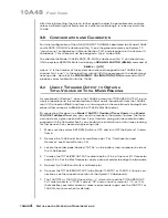
After this initial setting, there is no further need to adjust the potentiometer controls
unless a different type of flowmeter or a different cable length is to be used with the
10A48.
3.b C
ONFIGURATION AND
C
ALIBRATION
For initial configuration of the ANALOG INPUT CHANNEL dedicated to a Model 10A48
card’s RATE-OF-FLOW subchannel (No. 1), see the general remarks on System 10
“real-channel” configuration in Manual Section 1.G.1 and elsewhere in the System 10
Guidebook. This channel must be assigned a “type” code of
40
.
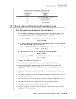
To calibrate the Model 10A48's RATE-OF-FLOW subchannel (No. 1), you should turn
ON the system EEPROM Switch and apply a
SCALING FACTOR (EMM)
command of
EMM x = i [CR]
where “x” is the number of the system data channel assigned to the 10A48's Sub-
channel No. 1 and “i” is the actual flow rate at 2000 Hz, expressed in the desired engi-
neering units. Note that the
FREQUENCY CALIBRATION (FRQ)
command will NOT
produce correct calibration for the 10A48.
3.c U
SE OF
T
OTALIZER
O
UTPUT TO
O
BTAIN A
T
OTAL
V
OLUME OR
T
OTAL
M
ASS
R
EADING
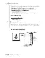
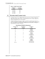
As mentioned in Section 1, above, the 10A48's pulse-train TOTALIZER OUTPUT is pre-
cisely proportional to the measured rate of flow, and is issued both from the 10A48's
rear I/O Connector (
Pin 4
) and from a wire-wrap pin on the mainframe's Analog Moth-
erboard that connects to
Pin 42
of the 10A48's Slot Connector.
By connecting this signal to a
Model 10ACT01 Counter/Timer Card
or to a
Model
10ACC-4 Totalizer Card
, you can count the number of flowmeter “pulses” that have
occurred over a given period of time. From this data, along with the calibration data
supplied with the flowmeter itself, you can obtain a total volume or total mass reading
for that period, in any desired engineering units.
1.
Make sure the system EEPROM Switch is OFF, and turn OFF the System 10 main-
frame.
2.
Remove the 10A48 card from its mainframe slot. For “Card Insertion and
Removal,” see Manual Section 1.B.
3.
Locate the solder pads labelled “TOTAL” on the bottom (non-component) side of
the 10A48 board.
4.
To make the TOTALIZER OUTPUT available both at Pin 4 of the rear I/O Connector
and at Pin 42 of the Slot Connector, apply a drop of solder to bridge the two pads.
5.
Reinsert the 10A48 card in its mainframe slot.
6.
Connect the TOTALIZER OUTPUT to the Model 10ACT01 or 10ACC-4 (for pin con-
nections, see the respective section of the System 10 Guidebook).
7.
The 10ACT01 or 10ACC-4 Channel No. “y” which is to read the TOTALIZER OUT-
PUT must be set to a “TYPE” code of “C2” and a count increment (1, 10, or 100)
that satisfies your total volume or mass requirements (again, see the 10ACT01 or
10ACC-4 manual section for details).
10A48
F
LOW
C
ARD
Summary of Contents for System 10
Page 31: ...GETTING YOUR SYSTEM 10 ON THE AIR SB 2 FOR A SIZED MAINFRAMES...
Page 67: ...GETTING YOUR SYSTEM 10 ON THE AIR SB 2 FOR B SIZED MAINFRAMES...
Page 122: ...THIS PAGE INTENTIONALLY BLANK...
Page 134: ...1 12 THIS PAGE INTENTIONALLY BLANK...
Page 142: ...1 20 THIS PAGE INTENTIONALLY BLANK...
Page 150: ...1 28 THIS PAGE INTENTIONALLY BLANK...
Page 174: ...10A16 4C 6 THIS PAGE INTENTIONALLY BLANK 10A16 4C QUAD PLATINUM RTD CARD...
Page 186: ...10A18 4C 8 THIS PAGE INTENTIONALLY BLANK 10A18 4C QUAD PLATINUM LINEAR RTD CARD...
Page 212: ...10A40 8 THIS PAGE INTENTIONALLY BLANK 10A40 FREQUENCY CARD...
Page 224: ...10A43 4 THIS PAGE INTENTIONALLY BLANK 10A43 DWELL ANGLE CARD...
Page 234: ...10A48 6 THIS PAGE INTENTIONALLY BLANK 10A48 FLOW CARD...
Page 242: ...10A61 2 4 THIS PAGE INTENTIONALLY BLANK 10A61 2 DUAL 4 20 MA CARD...
Page 252: ...10A63 2 6 THIS PAGE INTENTIONALLY BLANK 10A63 2 DUAL DC VOLTAGE CARD...
Page 270: ...10A69 4 6 THIS PAGE INTENTIONALLY BLANK 10A69 4 QUAD AC RMS CARD...
Page 276: ...10A70 2 6 THIS PAGE INTENTIONALLY BLANK 10A70 2 DUAL DC STRAIN GAGE CARD...
Page 288: ...10A72 2C 12 THIS PAGE INTENTIONALLY BLANK 10A72 2C ENHANCED DUAL DC STRAIN GAGE CARD...
Page 320: ...10A74 4C 18 THIS PAGE INTENTIONALLY BLANK 10A74 4C QUAD DC STRAIN GAGE TRACK HOLD CARD...
Page 342: ...10A96 8 THIS PAGE INTENTIONALLY BLANK 10A96 AMPLIFIED ACCELEROMETER VIBRATION CARD...
Page 362: ...AA30 4 12 THIS PAGE INTENTIONALLY BLANK AA30 4 QUAD LVDT CARD...
Page 374: ...AA41 2 4 12 THIS PAGE INTENTIONALLY BLANK AA41 2 AA41 4 DUAL QUAD FREQUENCY CARD...
Page 390: ...AA72 2 4 16 THIS PAGE INTENTIONALLY BLANK AA72 2 AA72 4 DUAL QUAD DC STRAIN GAGE CARD...
Page 394: ...1 32 THIS PAGE INTENTIONALLY BLANK...
Page 404: ...1 42 THIS PAGE INTENTIONALLY BLANK...


