S
ETUP AND
/
OR
O
PERATING
C
ONSIDERATIONS
10A72-2C.
5
E
NHANCED
D
UAL
DC S
TRAIN
G
AGE
C
ARD
10A72-2C
3
S
ETUP AND
/
OR
O
PERATING
C
ONSIDERATIONS
3.a S
ELECTION OF
C
ONDITIONER
M
ODES
When receiving input from a conventional 4-arm strain gage bridge, a 10A72-2C chan-
nel should remain in the factory-set “TRANSDUCER” mode. When conditioning input
from a 1/4-bridge (1-arm) or 1/2-bridge (2-arm) strain gage configuration, however,
the channel should be set to “GAGE” mode, as follows:*
1.
Remove the 10A72-2C card from its mainframe slot. For “Card Insertion and
Removal,” see Manual Section 1.B. Since the 10A72-2C is “hot-pluggable,” you
need NOT turn off mainframe power before removing the card.
2.
Refer to Fig. 3 and locate the CONDITIONER MODE PROGRAMMING JUMPER
PINS for Channels 1 and 2. One “minijumper” is provided for each channel, for
interconnecting adjacent jumper pins.
3.
Position the jumper for each channel as shown in Fig. 3 to set the desired mode
for that channel.
4.
Keep out the 10A72-2C card for the excitation selection procedure, below.
3.b S
ELECTION OF
E
XCITATION
L
EVELS
To set the DC excitation for each 10A72-2C channel, you should
1.
Refer to Fig. 3 and locate the EXCITATION VOLTAGE PROGRAMMING JUMPER
PINS for Channels 1 and 2. One “minijumper” is provided for each channel, for
interconnecting adjacent jumper pins.
2.
Position the jumper for each channel as shown in Fig. 3 to set the desired excita-
tion for that channel (1, 5, or 10 V).
3.
Keep out the 10A72-2C card for the filter selection procedure, below.
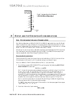
Fig. 2 Jumpering of an Unused
10A72-2C Strain Gage Input
+EX
(Chn. n)
+SEN
(Chn. n)
–EX
(Chn. n)
–SEN
(Chn. n)
+SIG
(Chn. n)
–SIG
(Chn. n)
Model 10A72-2C
I/O Connector
GROUND
LUG
* In “GAGE” mode, the 10A72-2C requires the connection of a
Model 10CJB-2 Dual Bridge
Completion Card
, or equivalent circuitry provided by the user (see Section 4). The purpose
of the “GAGE” setting is to ensure compatibility with special applications of the older Model
10A72-2 where it was not required that the “CAL SENSE” line be tied to the “+ SIGNAL” line.
Summary of Contents for System 10
Page 31: ...GETTING YOUR SYSTEM 10 ON THE AIR SB 2 FOR A SIZED MAINFRAMES...
Page 67: ...GETTING YOUR SYSTEM 10 ON THE AIR SB 2 FOR B SIZED MAINFRAMES...
Page 122: ...THIS PAGE INTENTIONALLY BLANK...
Page 134: ...1 12 THIS PAGE INTENTIONALLY BLANK...
Page 142: ...1 20 THIS PAGE INTENTIONALLY BLANK...
Page 150: ...1 28 THIS PAGE INTENTIONALLY BLANK...
Page 174: ...10A16 4C 6 THIS PAGE INTENTIONALLY BLANK 10A16 4C QUAD PLATINUM RTD CARD...
Page 186: ...10A18 4C 8 THIS PAGE INTENTIONALLY BLANK 10A18 4C QUAD PLATINUM LINEAR RTD CARD...
Page 212: ...10A40 8 THIS PAGE INTENTIONALLY BLANK 10A40 FREQUENCY CARD...
Page 224: ...10A43 4 THIS PAGE INTENTIONALLY BLANK 10A43 DWELL ANGLE CARD...
Page 234: ...10A48 6 THIS PAGE INTENTIONALLY BLANK 10A48 FLOW CARD...
Page 242: ...10A61 2 4 THIS PAGE INTENTIONALLY BLANK 10A61 2 DUAL 4 20 MA CARD...
Page 252: ...10A63 2 6 THIS PAGE INTENTIONALLY BLANK 10A63 2 DUAL DC VOLTAGE CARD...
Page 270: ...10A69 4 6 THIS PAGE INTENTIONALLY BLANK 10A69 4 QUAD AC RMS CARD...
Page 276: ...10A70 2 6 THIS PAGE INTENTIONALLY BLANK 10A70 2 DUAL DC STRAIN GAGE CARD...
Page 288: ...10A72 2C 12 THIS PAGE INTENTIONALLY BLANK 10A72 2C ENHANCED DUAL DC STRAIN GAGE CARD...
Page 320: ...10A74 4C 18 THIS PAGE INTENTIONALLY BLANK 10A74 4C QUAD DC STRAIN GAGE TRACK HOLD CARD...
Page 342: ...10A96 8 THIS PAGE INTENTIONALLY BLANK 10A96 AMPLIFIED ACCELEROMETER VIBRATION CARD...
Page 362: ...AA30 4 12 THIS PAGE INTENTIONALLY BLANK AA30 4 QUAD LVDT CARD...
Page 374: ...AA41 2 4 12 THIS PAGE INTENTIONALLY BLANK AA41 2 AA41 4 DUAL QUAD FREQUENCY CARD...
Page 390: ...AA72 2 4 16 THIS PAGE INTENTIONALLY BLANK AA72 2 AA72 4 DUAL QUAD DC STRAIN GAGE CARD...
Page 394: ...1 32 THIS PAGE INTENTIONALLY BLANK...
Page 404: ...1 42 THIS PAGE INTENTIONALLY BLANK...


