Since the equivalent input is here expressed as a percentage of full-scale output, you
must multiply it by the rated full-scale capacity of the transducer, in order to determine
the actual input simulated by the shunt.
Shunt calibration is an easier though generally less accurate technique then two-point
(deadweight) calibration. It is useful, however, when overall “deadweighting” is impos-
sible or inconvenient, and is good for an accuracy of about 0.2% (depending, of
course, on the accuracy of the specified equivalent input, and on the resistor/bridge
tolerance and temperature).
The 10A72-2C is equipped with a 100-k
Ω
, 0.1% calibration resistor for each active
channel. These resistors are located on turret terminals at the rear of the card (see
Fig. 4). You may, if you wish, replace each channel’s installed 100K shunt resistor with
a resistor of another value (strain-gage transducer manufacturers often supply such
resistors with their instruments).
In System 10, a strain gage channel’s shunt resistor may be switched in and out by
means of the
SHUNT CALIBRATE—POSITIVE (SHP)
or
SHUNT CALIBRATE—NEGA-
TIVE (SHN)
command. A
RESUME (RSM)
command should then be applied to
remove the shunt and resume normal channel measurement. Since these are “run-
time” commands, the mainframe’s
EEPROM Write Protect Switch
need not be on
for them to be effective. See Manual Section 1.G.6 for general instructions regarding
the “SHUNT CALIBRATION” technique in System 10.
NOTE:
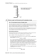
Per-channel shunt calibration for the 10A72-2C can be “remotely” controlled, if
desired, as an alternative to using the software “SHUNT CALIBRATE” commands pro-
vided by the system. This remote calibration control is accomplished by means of
logic-level inputs to the 10A72-2C card. The relevant connections are given in Fig. 5.
Fig. 5(a) shows how the “CALIBRATE POSITIVE” and “CALIBRATE NEGATIVE” com-
mands can be independely applied to either active 10A72-2C channel, without the
need of an external logic reference supply.
Closing the switch in Fig. 5(a) to contact point “A” will produce a Logic 0 level at Pin D
(“NOT +CALIBRATE”). Since this is a negative-true logic line, the Logic 0 input will acti-
vate the “+CALIBRATE” condition of the channel. That is, it will switch in the channel’s
shunt resistor for a positive up-scale reading. Opening the switch to disconnect the
“NOT +CALIBRATE” line from SIGNAL COMMON will then return the channel to the
“NO +CALIBRATE” condition.
Similarly, closing the switch to contact point “B” will produce a Logic 0 level at Pin E
(“NOT –CALIBRATE”), thereby switching in the channel’s shunt resistor for a negative
up-scale reading. Opening the switch to disconnect the “NOT –CALIBRATE” line from
SIGNAL COMMON will then return the channel to the “NO –CALIBRATE” condition.
You may also use active TTL logic, as illustrated in Fig. 5(b), to produce the “+CALI-
BRATE” or “–CALIBRATE” condition for either 10A72-2C channel.
10A72-2C.
8
S
ETUP AND
/
OR
O
PERATING
C
ONSIDERATIONS
10A72-2C
E
NHANCED
D
UAL
DC S
TRAIN
G
AGE
C
ARD
Rear I/O Connector
Side 2
Shunt Resistor
for Channel 1
(#R103)
Shunt Resistor
for Channel 2
(#R104)
Terminal post for connection of resistor
Fig. 4 Model
10A72-2C
Shunt
Calibration
Resistors
Summary of Contents for System 10
Page 31: ...GETTING YOUR SYSTEM 10 ON THE AIR SB 2 FOR A SIZED MAINFRAMES...
Page 67: ...GETTING YOUR SYSTEM 10 ON THE AIR SB 2 FOR B SIZED MAINFRAMES...
Page 122: ...THIS PAGE INTENTIONALLY BLANK...
Page 134: ...1 12 THIS PAGE INTENTIONALLY BLANK...
Page 142: ...1 20 THIS PAGE INTENTIONALLY BLANK...
Page 150: ...1 28 THIS PAGE INTENTIONALLY BLANK...
Page 174: ...10A16 4C 6 THIS PAGE INTENTIONALLY BLANK 10A16 4C QUAD PLATINUM RTD CARD...
Page 186: ...10A18 4C 8 THIS PAGE INTENTIONALLY BLANK 10A18 4C QUAD PLATINUM LINEAR RTD CARD...
Page 212: ...10A40 8 THIS PAGE INTENTIONALLY BLANK 10A40 FREQUENCY CARD...
Page 224: ...10A43 4 THIS PAGE INTENTIONALLY BLANK 10A43 DWELL ANGLE CARD...
Page 234: ...10A48 6 THIS PAGE INTENTIONALLY BLANK 10A48 FLOW CARD...
Page 242: ...10A61 2 4 THIS PAGE INTENTIONALLY BLANK 10A61 2 DUAL 4 20 MA CARD...
Page 252: ...10A63 2 6 THIS PAGE INTENTIONALLY BLANK 10A63 2 DUAL DC VOLTAGE CARD...
Page 270: ...10A69 4 6 THIS PAGE INTENTIONALLY BLANK 10A69 4 QUAD AC RMS CARD...
Page 276: ...10A70 2 6 THIS PAGE INTENTIONALLY BLANK 10A70 2 DUAL DC STRAIN GAGE CARD...
Page 288: ...10A72 2C 12 THIS PAGE INTENTIONALLY BLANK 10A72 2C ENHANCED DUAL DC STRAIN GAGE CARD...
Page 320: ...10A74 4C 18 THIS PAGE INTENTIONALLY BLANK 10A74 4C QUAD DC STRAIN GAGE TRACK HOLD CARD...
Page 342: ...10A96 8 THIS PAGE INTENTIONALLY BLANK 10A96 AMPLIFIED ACCELEROMETER VIBRATION CARD...
Page 362: ...AA30 4 12 THIS PAGE INTENTIONALLY BLANK AA30 4 QUAD LVDT CARD...
Page 374: ...AA41 2 4 12 THIS PAGE INTENTIONALLY BLANK AA41 2 AA41 4 DUAL QUAD FREQUENCY CARD...
Page 390: ...AA72 2 4 16 THIS PAGE INTENTIONALLY BLANK AA72 2 AA72 4 DUAL QUAD DC STRAIN GAGE CARD...
Page 394: ...1 32 THIS PAGE INTENTIONALLY BLANK...
Page 404: ...1 42 THIS PAGE INTENTIONALLY BLANK...


