10A73-4.
6
G
AGE
/ T
RANSDUCER
C
ONNECTIONS
10A73-4
Q
UAD
1/2 & 1/4 B
RIDGE
DC S
TRAIN
G
AGE
C
ARD
2.b 1/4-, 1/2-,
OR
F
ULL
-B
RIDGE
G
AGE
C
ONNECTIONS
U
SING THE
M
ODEL
10CJB-4
Remove the top plate of the Model 10CJB-4 box (4 screws in corners). Inside the box
are four sets of labelled screw terminals, one for each of the 10A73-4’s input channels
(“A,” “B,” “C,” and “D”). You will connect your gage wires directly to these terminals, as
shown in Fig. 3, and, if necessary, interconnect certain terminal pairs by means of
jumper wires. Gage leads should enter the 10CJB-4 through the cutout on the right-
hand side of the box.
NOTE: You must furnish your own pin-to-pin shielded cable for connecting the
10CJB-4 to the 10A73-4’s rear I/O CONNECTOR (see Table 2 for pin assignments)—or
you may use a special cable furnished by Daytronic. In either case, Daytronic will sup-
ply terminal connectors for the cable.
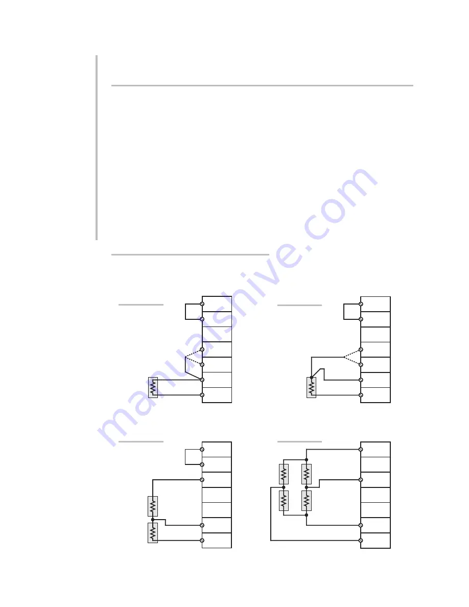
Fig. 3(a) shows connections between the 10CJB-4 and a 2-wire 1/4-bridge gage con-
figuration (represented by the single gage resistor). Here, you must install a jumper
wire between the
–SIG
and
1/2 BR
terminals, and between the
+SIG
terminal and
either the
120
terminal or the
350
terminal, depending on the nominal gage resis-
tance.
–SIG
1/2 BR
–EX
120
350
+SIG
+EX
Signal
Excitation
Model 10CJB-4
Screw Terminal
(Chn. 1, 2, 3, or 4)
Fig. 3(a)
2-Wire
1/4-Bridge
Completion
Model 10CJB-4
Screw Terminal
(Chn. 1, 2, 3, or 4)
–SIG
1/2 BR
–EX
120
350
+SIG
+EX
Signal
Excitation
Fig. 3(b)
3-Wire
1/4-Bridge
Completion
–SIG
1/2 BR
–EX
120
350
+SIG
+EX
Signal
+Excitation
–Excitation
Model 10CJB-4
Screw Terminal
(Chn. 1, 2, 3, or 4)
Fig. 3(c)
1/2-Bridge
Completion
–SIG
1/2 BR
–EX
120
350
+SIG
+EX
+Signal
+Excitation
–Excitation
–Signal
Model 10CJB-4
Screw Terminal
(Chn. 1, 2, 3, or 4)
Fig. 3(d)
Full-Bridge
Connection
Fig. 3 Model 10CJB-4 Transducer Cabling
Summary of Contents for System 10
Page 31: ...GETTING YOUR SYSTEM 10 ON THE AIR SB 2 FOR A SIZED MAINFRAMES...
Page 67: ...GETTING YOUR SYSTEM 10 ON THE AIR SB 2 FOR B SIZED MAINFRAMES...
Page 122: ...THIS PAGE INTENTIONALLY BLANK...
Page 134: ...1 12 THIS PAGE INTENTIONALLY BLANK...
Page 142: ...1 20 THIS PAGE INTENTIONALLY BLANK...
Page 150: ...1 28 THIS PAGE INTENTIONALLY BLANK...
Page 174: ...10A16 4C 6 THIS PAGE INTENTIONALLY BLANK 10A16 4C QUAD PLATINUM RTD CARD...
Page 186: ...10A18 4C 8 THIS PAGE INTENTIONALLY BLANK 10A18 4C QUAD PLATINUM LINEAR RTD CARD...
Page 212: ...10A40 8 THIS PAGE INTENTIONALLY BLANK 10A40 FREQUENCY CARD...
Page 224: ...10A43 4 THIS PAGE INTENTIONALLY BLANK 10A43 DWELL ANGLE CARD...
Page 234: ...10A48 6 THIS PAGE INTENTIONALLY BLANK 10A48 FLOW CARD...
Page 242: ...10A61 2 4 THIS PAGE INTENTIONALLY BLANK 10A61 2 DUAL 4 20 MA CARD...
Page 252: ...10A63 2 6 THIS PAGE INTENTIONALLY BLANK 10A63 2 DUAL DC VOLTAGE CARD...
Page 270: ...10A69 4 6 THIS PAGE INTENTIONALLY BLANK 10A69 4 QUAD AC RMS CARD...
Page 276: ...10A70 2 6 THIS PAGE INTENTIONALLY BLANK 10A70 2 DUAL DC STRAIN GAGE CARD...
Page 288: ...10A72 2C 12 THIS PAGE INTENTIONALLY BLANK 10A72 2C ENHANCED DUAL DC STRAIN GAGE CARD...
Page 320: ...10A74 4C 18 THIS PAGE INTENTIONALLY BLANK 10A74 4C QUAD DC STRAIN GAGE TRACK HOLD CARD...
Page 342: ...10A96 8 THIS PAGE INTENTIONALLY BLANK 10A96 AMPLIFIED ACCELEROMETER VIBRATION CARD...
Page 362: ...AA30 4 12 THIS PAGE INTENTIONALLY BLANK AA30 4 QUAD LVDT CARD...
Page 374: ...AA41 2 4 12 THIS PAGE INTENTIONALLY BLANK AA41 2 AA41 4 DUAL QUAD FREQUENCY CARD...
Page 390: ...AA72 2 4 16 THIS PAGE INTENTIONALLY BLANK AA72 2 AA72 4 DUAL QUAD DC STRAIN GAGE CARD...
Page 394: ...1 32 THIS PAGE INTENTIONALLY BLANK...
Page 404: ...1 42 THIS PAGE INTENTIONALLY BLANK...


