3.
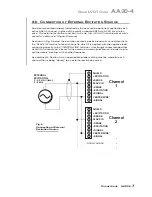
Position the jumper for each channel as shown in Fig. 5 to interconnect the pair of
pins corresponding to the desired “open TC” polarity for that channel. You will
need to use a small pair of needle-nosed pliers to move the jumper.
4.
Reinsert the AA14-4F010 card in its mainframe slot.
3.b S
ELECTION OF
A
NALOG
O
UTPUT
M
ODES
As mentioned in Section 1, each AA14-4F010 channel's ±5-V ANALOG OUTPUT can
be set to represent either the filtered or prefiltered reading of that channel. To set the
output mode for each of your AA14-4F010's active input channels,* you should
1.
Remove the AA14-4F010 card from its slot (see Section 3.a, Step 1, above).
2.
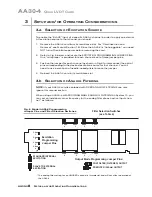
Refer to Fig. 5 and locate the OUTPUT MODE PROGRAMMING JUMPER PINS
beneath the AA14-4F010's Filter Tile(s). One “minijumper” is provided for each
channel's set of three jumper pins.
3.
Position the jumper for each channel as shown in Fig. 5 to interconnect the pair of
pins that corresponds to the desired output mode for that channel. You will need
to use a small pair of needle-nosed pliers to move the jumper.
4.
Reinsert the AA14-4F010 card in its mainframe slot.
3.c C
ONFIGURATION AND
C
ALIBRATION
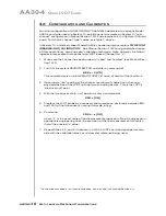
For initial configuration of ANALOG INPUT CHANNELS dedicated to a specific Model
AA14-4F010
card, see the general remarks on System 10 “real-channel” configura-
tion in Manual Section 1.G.1 and elsewhere in the System 10 Guidebook. For
AA14-
4F010
channel “type” codes, see Table 3, below.
In System 10, the initial configuration and
ABSOLUTE CALIBRATION
of an
AA14-4F010 channel (No. “x”) involve direct entry of the channel’s TYPE CODE,
SCALING FACTOR (“m” coefficient), and ZERO OFFSET (“b” term) via the corre-
sponding mnemonic commands. The values of these parameters that are
entered will depend on the TC type and the desired engineering units (°C or °F),
as given in Table 3, below. You may also perform a subsequent
TWO-POINT
(DEADWEIGHT)
calibration of an AA14-4F010 channel in System 10, as
explained below.
A
BSOLUTE
C
ALIBRATION
In the following procedure, Channel No. “x” is a System 10 “REAL CHANNEL”
sourced by an AA14-4F010 card. Note that, with the exception of the
LOCATE
(LCT)
command (Step 2), each of the commands can be applied to a continuous
range of channels by entering the command in “range” form, where the single
channel-number argument “x” is replaced by “x TO y” (indicating all channels
from Channel No. x to and including Channel No. y).
1.
Turn ON the system EEPROM SWITCH.
2.
Make sure that Channel No. x has been assigned the proper A-SLOT / SUB-
CHANNEL “location.” See Manual Section 1.G.1 for details on the
LOCATE
(LCT)
command.
AA14-4F010.
6
S
ETUP AND
/
OR
O
PERATING
C
ONSIDERATIONS
* The output mode setting for an UNUSED channel is immaterial, and will not affect operation of
the AA14-4F010.
AA14-4F010
T
HERMOCOUPLE
C
ARD
Summary of Contents for System 10
Page 31: ...GETTING YOUR SYSTEM 10 ON THE AIR SB 2 FOR A SIZED MAINFRAMES...
Page 67: ...GETTING YOUR SYSTEM 10 ON THE AIR SB 2 FOR B SIZED MAINFRAMES...
Page 122: ...THIS PAGE INTENTIONALLY BLANK...
Page 134: ...1 12 THIS PAGE INTENTIONALLY BLANK...
Page 142: ...1 20 THIS PAGE INTENTIONALLY BLANK...
Page 150: ...1 28 THIS PAGE INTENTIONALLY BLANK...
Page 174: ...10A16 4C 6 THIS PAGE INTENTIONALLY BLANK 10A16 4C QUAD PLATINUM RTD CARD...
Page 186: ...10A18 4C 8 THIS PAGE INTENTIONALLY BLANK 10A18 4C QUAD PLATINUM LINEAR RTD CARD...
Page 212: ...10A40 8 THIS PAGE INTENTIONALLY BLANK 10A40 FREQUENCY CARD...
Page 224: ...10A43 4 THIS PAGE INTENTIONALLY BLANK 10A43 DWELL ANGLE CARD...
Page 234: ...10A48 6 THIS PAGE INTENTIONALLY BLANK 10A48 FLOW CARD...
Page 242: ...10A61 2 4 THIS PAGE INTENTIONALLY BLANK 10A61 2 DUAL 4 20 MA CARD...
Page 252: ...10A63 2 6 THIS PAGE INTENTIONALLY BLANK 10A63 2 DUAL DC VOLTAGE CARD...
Page 270: ...10A69 4 6 THIS PAGE INTENTIONALLY BLANK 10A69 4 QUAD AC RMS CARD...
Page 276: ...10A70 2 6 THIS PAGE INTENTIONALLY BLANK 10A70 2 DUAL DC STRAIN GAGE CARD...
Page 288: ...10A72 2C 12 THIS PAGE INTENTIONALLY BLANK 10A72 2C ENHANCED DUAL DC STRAIN GAGE CARD...
Page 320: ...10A74 4C 18 THIS PAGE INTENTIONALLY BLANK 10A74 4C QUAD DC STRAIN GAGE TRACK HOLD CARD...
Page 342: ...10A96 8 THIS PAGE INTENTIONALLY BLANK 10A96 AMPLIFIED ACCELEROMETER VIBRATION CARD...
Page 362: ...AA30 4 12 THIS PAGE INTENTIONALLY BLANK AA30 4 QUAD LVDT CARD...
Page 374: ...AA41 2 4 12 THIS PAGE INTENTIONALLY BLANK AA41 2 AA41 4 DUAL QUAD FREQUENCY CARD...
Page 390: ...AA72 2 4 16 THIS PAGE INTENTIONALLY BLANK AA72 2 AA72 4 DUAL QUAD DC STRAIN GAGE CARD...
Page 394: ...1 32 THIS PAGE INTENTIONALLY BLANK...
Page 404: ...1 42 THIS PAGE INTENTIONALLY BLANK...


