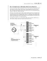
a.
Remove the AA30-4 card from its slot (see Section 3.a, Step 1, above).
b.
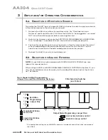
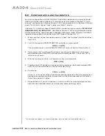
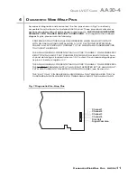
Refer to Fig. 6 and locate the 16-position FILTER SELECTION SWITCHES located
between the main card and the Filter Tiles.
c.
Referring to Table 4, below, set each channel's switch for the desired frequency.
You will need to use a small screwdriver (or equivalent tool) to set the switch to the
appropriate number/letter.
d.
Reinsert the AA30-4 card.
NOTE:
In addition to the normal-mode analog filtering supplied by the AA30-4 card,
System 10 can provide additional processor-controlled DIGITAL SMOOTHING on a
per-channel basis. For each individual channel, you may indicate the desired amount
of digital smoothing by applying a
FILTER (FIL)
command to that channel (see Manual
Section 2.G.2).
Table 4 Model AA30-4 Filter Switch Settings
Cutoff Frequency
Switch Setting
0.2 Hz
7
0.4 Hz
6
0.8 Hz
5
1.0 Hz
3
1.6 Hz
4
2.0 Hz
2
4.0 Hz
1
5.0 Hz
F
8.0 Hz
0
10 Hz
E
20 Hz
D
25 Hz
B
40 Hz
C
50 Hz
A
100 Hz
9
200 Hz
8
3.c S
ELECTION OF
A
NALOG
O
UTPUT
M
ODES
As mentioned in Section 1, each AA30-4 channel's ±5-V ANALOG OUTPUT can be set
to represent either the filtered or prefiltered reading of that channel. To set the output
mode for each of your AA30-4's active input channels,* you should
1.
Remove the AA30-4 card from its slot (see Section 3.a, Step 1, above).
2.
Refer to Fig. 6 and locate the OUTPUT MODE PROGRAMMING JUMPER PINS
beneath the AA30-4's Filter Tiles. One “minijumper” is provided for each channel's
set of three jumper pins.
3.
Position the jumper for each channel as shown in Fig. 6 to interconnect the pair of
pins that corresponds to the desired output mode for that channel. You will need
to use a small pair of needle-nosed pliers to move the jumper.
4.
Reinsert the AA30-4 card in its mainframe slot.
S
ETUP AND
/
OR
O
PERATING
C
ONSIDERATIONS
AA30-4.
9
Q
UAD
LVDT C
ARD
AA30-4
* The output mode setting for an UNUSED channel is immaterial, and will not affect operation of
the AA30-4.
Summary of Contents for System 10
Page 31: ...GETTING YOUR SYSTEM 10 ON THE AIR SB 2 FOR A SIZED MAINFRAMES...
Page 67: ...GETTING YOUR SYSTEM 10 ON THE AIR SB 2 FOR B SIZED MAINFRAMES...
Page 122: ...THIS PAGE INTENTIONALLY BLANK...
Page 134: ...1 12 THIS PAGE INTENTIONALLY BLANK...
Page 142: ...1 20 THIS PAGE INTENTIONALLY BLANK...
Page 150: ...1 28 THIS PAGE INTENTIONALLY BLANK...
Page 174: ...10A16 4C 6 THIS PAGE INTENTIONALLY BLANK 10A16 4C QUAD PLATINUM RTD CARD...
Page 186: ...10A18 4C 8 THIS PAGE INTENTIONALLY BLANK 10A18 4C QUAD PLATINUM LINEAR RTD CARD...
Page 212: ...10A40 8 THIS PAGE INTENTIONALLY BLANK 10A40 FREQUENCY CARD...
Page 224: ...10A43 4 THIS PAGE INTENTIONALLY BLANK 10A43 DWELL ANGLE CARD...
Page 234: ...10A48 6 THIS PAGE INTENTIONALLY BLANK 10A48 FLOW CARD...
Page 242: ...10A61 2 4 THIS PAGE INTENTIONALLY BLANK 10A61 2 DUAL 4 20 MA CARD...
Page 252: ...10A63 2 6 THIS PAGE INTENTIONALLY BLANK 10A63 2 DUAL DC VOLTAGE CARD...
Page 270: ...10A69 4 6 THIS PAGE INTENTIONALLY BLANK 10A69 4 QUAD AC RMS CARD...
Page 276: ...10A70 2 6 THIS PAGE INTENTIONALLY BLANK 10A70 2 DUAL DC STRAIN GAGE CARD...
Page 288: ...10A72 2C 12 THIS PAGE INTENTIONALLY BLANK 10A72 2C ENHANCED DUAL DC STRAIN GAGE CARD...
Page 320: ...10A74 4C 18 THIS PAGE INTENTIONALLY BLANK 10A74 4C QUAD DC STRAIN GAGE TRACK HOLD CARD...
Page 342: ...10A96 8 THIS PAGE INTENTIONALLY BLANK 10A96 AMPLIFIED ACCELEROMETER VIBRATION CARD...
Page 362: ...AA30 4 12 THIS PAGE INTENTIONALLY BLANK AA30 4 QUAD LVDT CARD...
Page 374: ...AA41 2 4 12 THIS PAGE INTENTIONALLY BLANK AA41 2 AA41 4 DUAL QUAD FREQUENCY CARD...
Page 390: ...AA72 2 4 16 THIS PAGE INTENTIONALLY BLANK AA72 2 AA72 4 DUAL QUAD DC STRAIN GAGE CARD...
Page 394: ...1 32 THIS PAGE INTENTIONALLY BLANK...
Page 404: ...1 42 THIS PAGE INTENTIONALLY BLANK...


