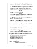
screen, pressing the
Ctrl
(CONTROL) key, and holding it down as you
press the
Insrt
(INSERT) key. Similarly, to delete an entire line of display,
move the cursor to the extreme left of the line to be deleted, press
Ctrl
,
and hold it down as you press
Dlete
(DELETE).
9.
Now set the line character size to “2x2” by
a.
First pressing the
Width
key and then 2.
b.
Then pressing the
Hght
(HEIGHT) key and then 2.
10. Set a color for the second line of your display—say, yellow on black:
[SHIFT], YELLOW, BACKGROUND, BLACK, [UNSHIFT]
11. Insert a whole line of black spaces at the cursor position, as described in
Step 8, above, by pressing
<Ctrl> Insrt
.
12. To enter the first portion of FIXED TEXT for the second line, type several
spaces (via the SPACE BAR) and the word “
BOOST:
”
13. To start the DATA FIELD that immediately follows “BOOST:,” press the
Begin Data
key.
14. Enter four spaces and then
001
, which is the channel number that identi-
fies this data field. Remember that the last digit of the channel-number
entry must always occupy the last character space of the data field.
15. Press the
End Data
key. You have now established a seven-space data
field. This field will normally appear as blue characters on a green back-
ground as long as you’re in the TEXT EDITOR MODE. NOTE: If you should
make an error in entering the data field, you will be alerted by a specific
“prompting message” in the billboard (see Section 2.C.5(e) of the System
10 Guidebook for details).
16. Now enter the remaining FIXED TEXT for this line: one space, followed by
the unit legend “
IN HG
.” Since the whole line was inserted in Step 11 (with
the foreground/background combination specified in Step 10), the letters
will appear in the same color as the word “BOOST:” It is permissible, how-
ever, to specify a new color at any point within a given line’s FIXED TEXT.
(In fact, if you had not entered the whole line in Step 11, you would have to
reset the desired color upon leaving the data field.)
17. Press CARRIAGE RETURN (
Retrn
) twice, and follow the same procedure
to enter the second and third data lines (entering channel numbers of
002
and
003
, respectively). NOTE: While you must reset the character size for
each succeeding line, you need not reset the color, so long as you exit the
original line by pressing CARRIAGE RETURN. Remember, too, to use the
Insrt
and
Dlete
keys for horizontal positioning of each line, as in Steps 5
and 7, above.
18. When you’re satisfied with the appearance of your display format, press
the
Exit
key to leave TEXT EDITOR MODE and return to LIVE DISPLAY
MODE.
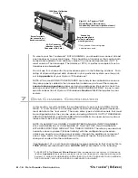
As shown in Fig. 5.1.b, the channel numbers you entered in the display’s
data fields will now be replaced by “live” data readings for the respective
channels, while the color of each data field will now change to the color
determined by the “STATUS”-defining command currently in effect for the
respective channel. Unless otherwise specified by the purchaser, each
mainframe is shipped with an initial status setting of white on black for
every data channel, for all limit conditions.
B - 13
CRT V
IDEO
S
ETUP
“O
N THE
A
IR
” (B-S
IZED
)
Summary of Contents for System 10
Page 31: ...GETTING YOUR SYSTEM 10 ON THE AIR SB 2 FOR A SIZED MAINFRAMES...
Page 67: ...GETTING YOUR SYSTEM 10 ON THE AIR SB 2 FOR B SIZED MAINFRAMES...
Page 122: ...THIS PAGE INTENTIONALLY BLANK...
Page 134: ...1 12 THIS PAGE INTENTIONALLY BLANK...
Page 142: ...1 20 THIS PAGE INTENTIONALLY BLANK...
Page 150: ...1 28 THIS PAGE INTENTIONALLY BLANK...
Page 174: ...10A16 4C 6 THIS PAGE INTENTIONALLY BLANK 10A16 4C QUAD PLATINUM RTD CARD...
Page 186: ...10A18 4C 8 THIS PAGE INTENTIONALLY BLANK 10A18 4C QUAD PLATINUM LINEAR RTD CARD...
Page 212: ...10A40 8 THIS PAGE INTENTIONALLY BLANK 10A40 FREQUENCY CARD...
Page 224: ...10A43 4 THIS PAGE INTENTIONALLY BLANK 10A43 DWELL ANGLE CARD...
Page 234: ...10A48 6 THIS PAGE INTENTIONALLY BLANK 10A48 FLOW CARD...
Page 242: ...10A61 2 4 THIS PAGE INTENTIONALLY BLANK 10A61 2 DUAL 4 20 MA CARD...
Page 252: ...10A63 2 6 THIS PAGE INTENTIONALLY BLANK 10A63 2 DUAL DC VOLTAGE CARD...
Page 270: ...10A69 4 6 THIS PAGE INTENTIONALLY BLANK 10A69 4 QUAD AC RMS CARD...
Page 276: ...10A70 2 6 THIS PAGE INTENTIONALLY BLANK 10A70 2 DUAL DC STRAIN GAGE CARD...
Page 288: ...10A72 2C 12 THIS PAGE INTENTIONALLY BLANK 10A72 2C ENHANCED DUAL DC STRAIN GAGE CARD...
Page 320: ...10A74 4C 18 THIS PAGE INTENTIONALLY BLANK 10A74 4C QUAD DC STRAIN GAGE TRACK HOLD CARD...
Page 342: ...10A96 8 THIS PAGE INTENTIONALLY BLANK 10A96 AMPLIFIED ACCELEROMETER VIBRATION CARD...
Page 362: ...AA30 4 12 THIS PAGE INTENTIONALLY BLANK AA30 4 QUAD LVDT CARD...
Page 374: ...AA41 2 4 12 THIS PAGE INTENTIONALLY BLANK AA41 2 AA41 4 DUAL QUAD FREQUENCY CARD...
Page 390: ...AA72 2 4 16 THIS PAGE INTENTIONALLY BLANK AA72 2 AA72 4 DUAL QUAD DC STRAIN GAGE CARD...
Page 394: ...1 32 THIS PAGE INTENTIONALLY BLANK...
Page 404: ...1 42 THIS PAGE INTENTIONALLY BLANK...


