WORLD RECORD BREAKING TECHNOLOGY
03
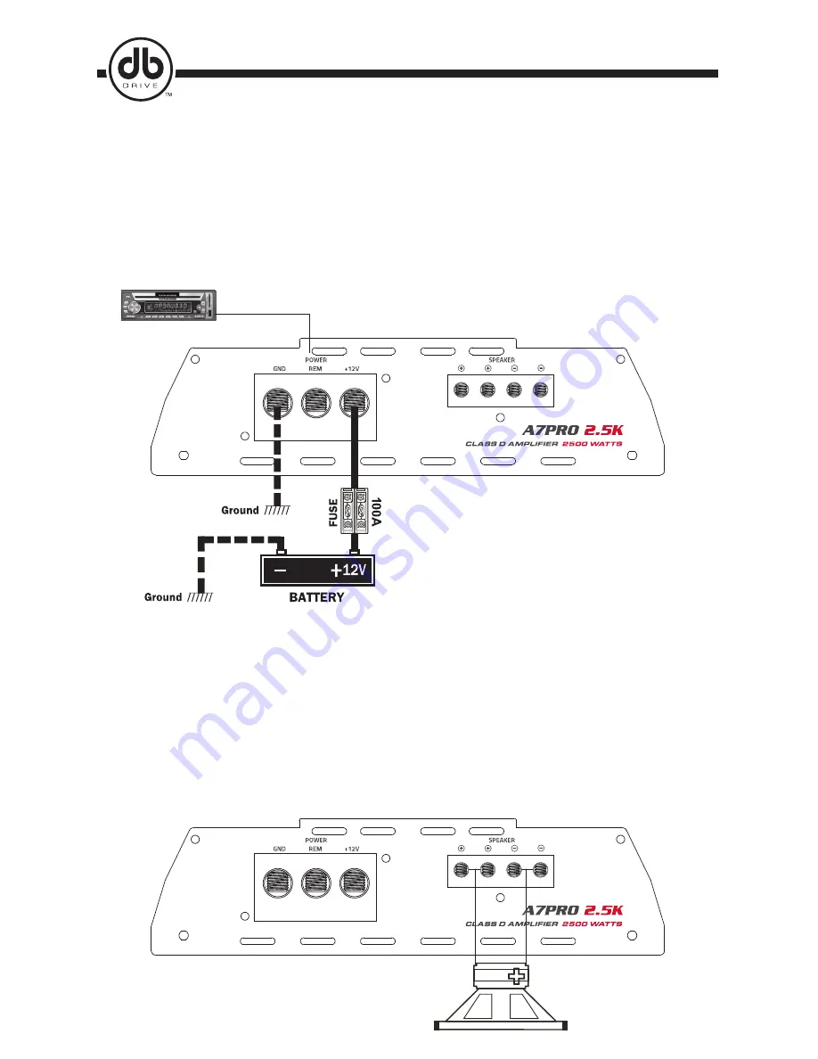
Remote turn on
CLASS D MONO AMPLIFIERS’ SPEAKER CONNECTION DIAGRAM 1.
8 ~ 1 ohms
GND ( GROUND CONNECTION )
Locate a secure grounding connection as close as possible. Make sure the location is clean and provides a direct
electrical connection to the frame of the vehicle.
Connect one end of a short piece of the same gauge cable as the power cable to the grounding point.
Run the one end of the cable to the grounding point. Run the other end of the cable to the mounting location.
Connect the ground cable to the screw terminal labeled as GND.
REM ( REMOTE CONNECTION )
Run a remote turn on cable from the headunit’s remote s12V output.
3-4. SPEAKER CONNECTION
DB Drive recommends to use minimum 12 gauge speaker connecting cables. Run 12 gauge speaker
connecting cables from your speakers to amplifier’s mounting location.
Keep speaker cables away from the power cables and amplifier’s input cables. Use grommets anywhere
the cables have to pass through the holes in the metal frame or sheet metal. Connect to the speakers
according to the type of terminals on each speaker. Strip 3/8” of insulation from the end of each cable and
twist the cables strands together tightly. Make sure there are no stray strands that might touch other cables
or terminals and cause a short circuit.
Crimp spade lugs over the cable ends or tin the ends with solder to provide a secure termination.
Connect the cable ends to amplifier as speaker system diagram.
AMP12V, GROUND, REMOTE CONNECTION DIAGRAM
Summary of Contents for A7PRO 2.5K
Page 6: ...P...


