background image


16 

DEUTSCH 

MERKMALE UND SCHUTZ 
 
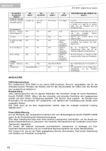
Angaben der Betriebsmodi, der Fehler und Schutzvorrichtungen 
Die  Leuchtanzeigen  (LEDs)  "READY",  "MUTE/PROT",  "SIGNAL"  und  "LIMIT"  werden  auch 
benutzt,  um  unterschiedliche  Betriebsweisen  und  unterschiedliche  Fehlertypen  mittels 
Blinkfrequenzen anzuzeigen, wie dies in nachstehender Diagnosetabelle aufgeführt ist. 
Bei den drei Störungsarten handelt es sich um: 

ACHTUNG:  Es  wurde  ein  leichter  Fehler  oder  eine  leichte  Funktionsstörung  mit 
automatischer  Rücksetzung  festgestellt  und  die  Leistungen  des  Verteilers  werden  nicht 
eingeschränkt. 

BEGRENZUNG:  Bei  Ermittlung  einer  Störung  werden  die  Leistungen  des  Funktionen 
reduziert. Der Schallpegel wird verringert bzw. einer oder mehr Verstärker werden deaktiviert. 
Dieser  Zustand  kann  sich  teilweise  auf  die  korrekte  Betriebsweise  des  Lautsprechers 
auswirken.  Falls  das  Problem  auch  bei  einem  späteren  Gebrauch  des  Moduls  weiterhin 
besteht, muss der Kundendienst eingeschaltet werden, um die Störung zu beheben. 

DEFEKT:  Es  wurde  eine  schwere  Funktionsstörung  festgestellt.  Der  Verteiler  wird  in  den 
Status “Mute” geschaltet.  

Im Störungsfall sollte man vor der Benachrichtigung des Kundendienstes das Modul zunächst aus- 
und erneut einschalten, um zu überprüfen, ob das Problem nach wie vor vorhanden ist. 
Kühlung 
Die Kühlung des Verstärkers am Lautsprecher DVA M2M erfolgt durch Konvektion an den internen 
Ableitern, ohne Hilfe von Lüftern. 
Der  Hitzeschutz  wird  durch  einen  internen  Schaltkreis  garantiert,  der  die  Temperatur  des 
Verstärkers  selbst  kontrolliert  und  ihn  vor  Überhitzungen  schützt,  indem  er  die  allgemeine 
Lautstärke begrenzt. 
Dieser Eingriff wird durch das Blinken der gelben Leuchtanzeige "MUTE/PROT" angezeigt. 
Das  korrekte  Volumen  und  alle  Funktionen  werden  automatisch  wieder  aufgenommen,  wenn  die 
normalen Betriebstemperaturen wieder erreicht wurden.  
Schutz 
Das  Aufleuchten  der  gelben  Kontrolllampe  “MUTE/PROT”  bedeutet,  dass  der  Verstärker  eine 
Funktionsstörung  des  Lautsprechers  festgestellt  und  diesen  daher  in  den  Mute-  Zustand  versetzt 
hat. 
In diesem Fall ist folgendes zu überprüfen: 
-  

Den korrekten Anschluss an das Stromnetz kontrollieren 

Sicher stellen, dass die richtige Versorgungsspannung vorliegt 

-  

Kontrollieren, dass der Verstärker nicht überhitzt ist. 

-  

Den  Lautsprecher  vom  Stromnetz  trennen,  einige  Minuten  abwarten  und  ihn  dann 
nochmals  anschließen.  

Wenn  die  Kontrolllampe  auch  nach  dieser  Wartezeit  nicht  erlischt,  bitte  eine  qualifizierte 
Kundendienststelle kontaktieren. 
 
DIAGNOSETABELLE 


STATUS ODER 
ZUSTAND DES 

MODULS 

LED 

“READY” 

LED 

“MUTE/PROT” 

LED 

“SIGNAL” 

LED 

“LIMITER” 

FUNKTIONEN ODER BESCHREIBUNG DES 

MODULS 

Normaler Betrieb 

Einschaltvorgang 

AUS 

EIN für  5 sec. 

AUS 

AUS 

Audio in MUTE  
Initialisierung des Verstärkermoduls 

Normalbetrieb 

EIN 

AUS 

Normalbetrieb 

Normalbetrieb 

Audio EIN 
Initialisierung 

des 

Moduls 

erfolgreich 

durchgeführt 

Partialfehler 

EIN 

Zyklisches 
Blinken 

Normalbetrieb 

Normalbetrieb 

Audio EIN 
Das Modul hat eine teilweise Störung ermittelt 
bleibt  mit  eingeschränkter  Betriebsweise 
aktiviert 

Gesamtfehler 

AUS 

EIN 

AUS 

Zyklisches 
Blinken 

Audio in MUTE 
Das Modul hat eine schwere Störung ermittelt 
und bleibt im Schutzmodus 

Summary of Contents for DVA M2M

Page 1: ...sere osservate congiuntamente al MANUALE D USO Sezione2 The warnings in this manual must be observed together with the USER MANUAL Section 2 Die Warnungen in diesem Handbuch m ssen in Verbindung mit d...

Page 2: ...iter e le segnalazioni del diffusore La PSU Power Supply Unit SMPS Switched Mode Power Supply grazie alla tecnologia auto range garantisce il funzionamento a tensioni di alimentazioni da 100V a 120V e...

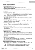
Page 3: ...olore verde per indicare che la tensione di alimentazione di rete corretta Nel normale funzionamento il led acceso in caso lampeggi o sia spento fare riferimento alla tabella della diagnostica per la...

Page 4: ...o un POWER CON grigio 13 PORTA FUSIBILE MAINS FUSE Alloggio per fusibile di rete DVA M2S Funzioni e Comandi Sezione Slave Audio Input 1 Ingresso amplificato per il diffusore DVA M2S connettore a 5 pol...

Page 5: ...e lo protegge dal surriscaldamento limitando il volume generale Questo intervento viene segnato tramite il lampeggio dell indicatore luminoso giallo MUTE PROT Il corretto volume e tutte le funzioni v...

Page 6: ...versione del pre amplificatore Modalit USB Funzione di bootoader attiva Spento Spento Lampeggiano alternativamente E attiva la funzione di bootloader nel pre amplificatore Telemetria attiva Lampeggian...

Page 7: ...50 60Hz Corrente di accensione 20 6A Consumo di corrente 100 120Vac 50 60Hz 220 240Vac 50 60Hz 1A 0 5A Dimensioni LxHxP 460x190x345mm 18 1x7 5x13 6 inch 460x190x345mm 18 1x7 5x13 6 inch Peso 7 7Kg 16...

Page 8: ...Power Supply Power Supply Unit PSU thanks to its self range technology ensures operation at supply voltages from 100V to 120V and from 220V to 240V Both speakers are provided with the same acoustic c...

Page 9: ...dicate that the main power voltage is correct In normal operating conditions the LED is on if it flashes or is off refer to the diagnostics table Audio Input control section 8 INPUT SENS INPUT SENSITI...

Page 10: ...RIER Mains fuse housing DVA M2S Functions and controls Slave Audio Input section 1 Amplified input for the speaker DVA M2S 5 pole connector The connection between the speakers DVA M2M and DVA M2S is r...

Page 11: ...heating by limiting the overall volume This intervention is marked by the flashing of a yellow indicator light MUTE PROT The correct volume and all the functions will be automatically restarted after...

Page 12: ...pre amplifier is active Telemetry ON They flash alternately OFF OFF The amplifier module is connected to the USB port for downloading the telemetry CONNECTIONS USB Data Link The speaker DVA M2M is equ...

Page 13: ...50 60Hz Inrush current 20 6A Current consumption 100 120Vac 50 60Hz 220 240Vac 50 60Hz 1A 0 5A Dimensions LxHxP 460x190x345mm 18 1x7 5x13 6 inch 460x190x345mm 18 1x7 5x13 6 inch Weight 7 7Kg 16 8lbs...

Page 14: ...den Limiter und die Signalisierungen des Lautsprechers Die PSU Power Supply Unit SMPS Switches Mode Power Supply garantiert Dank der Auto Range Technologie die Funktion bei Versorgungsspannungen von 1...

Page 15: ...wenn sie blinkt oder ausgeschaltet ist kann man der Diagnosetabelle Informationen zur Kontrolle des Zustands des Verst rkers entnehmen Abschnitt Audio Input Control 7 EMPFINDLICHKEITSREGLER EINGANG IN...

Page 16: ...N grau 13 SICHERUNGSHALTER MAINS FUSE Er enth lt die Netzsicherung DVA M2S Funktionen und Bedienelemente Abschnitt Slave Audio Input 1 Eingang Verst rker f r Lautsprecher DVA M2S 5 poliger Steckverbin...

Page 17: ...ert der die Temperatur des Verst rkers selbst kontrolliert und ihn vor berhitzungen sch tzt indem er die allgemeine Lautst rke begrenzt Dieser Eingriff wird durch das Blinken der gelben Leuchtanzeige...

Page 18: ...Telemetrie aktiv Abwechselndes Blinken AUS AUS Das Verst rkermodul ist am USB Anschluss angeschlossen um die Telemetrie herunterzuladen ANSCHL SSE USB Datenanschluss Der Lautsprecher DVA M2M ist mit...

Page 19: ...50 60Hz Einschaltstrom 20 6A Stromaufnahme 100 120Vac 50 60Hz 220 240Vac 50 60Hz 1A 0 5A Abmessungen BxHxT 460x190x345mm 18 1x7 5x13 6 inch 460x190x345mm 18 1x7 5x13 6 inch Gewicht 7 7Kg 16 8lbs 7 1Kg...

Page 20: ...r ponse en fr quence le limiteur et les signalisations du diffuseur La PSU Power Supply Unit SMPS Switched Mode Power Supply gr ce la technologie auto range plage de mesure automatique garantit le fo...

Page 21: ...rte pour indiquer que la tension d alimentation de r seau est correcte Pendant le fonctionnement normal la LED est allum e si elle clignote ou si elle est teinte se r f rer au tableau de diagnostic po...

Page 22: ...POWER CON gris 13 BLOC FUSIBLE MAINS FUSE Logement pour le fusible de r seau DVA M2S Fonctions et commandes Section Slave Audio Input 1 Entr e amplifi e pour le diffuseur DVA M2S connecteur 5 p les Le...

Page 23: ...mplificateur et le prot ge contre la surchauffe en limitant le volume g n ral Cette intervention est indiqu e par le clignotement du voyant lumineux jaune MUTE PROT Le volume correct et toutes les fon...

Page 24: ...ent La fonction de bootloader dans le pr amplificateur est active T l m trie active Clignotent alternativement teint teint Le module amplificateur est reli au port USB pour le t l chargement de la t l...

Page 25: ...40Vac 50 60Hz Courant d appel 20 6A Consommation de courant 100 120Vac 50 60Hz 220 240Vac 50 60Hz 1A 0 5A Dimensions WxHxD 460x190x345mm 18 1x7 5x13 6 inch 460x190x345mm 18 1x7 5x13 6 inch Poids 7 7Kg...

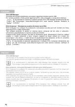
Page 26: ...Si raccomanda di scaricare gratuitamente il software DVA_Composer direttamente dal sito dB Technologies www dbtechnologies com nella sezione dedicata Software Controller DVA USB Manager The firmware o...

Page 27: ...n der Webseite dB Technologies www dbtechnologies com im Abschnitt software Controller herunterzuladen DVA USB Manager Le micrologiciel du module amplificateur peut tre remis jour par le port USB Pour...

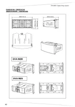
Page 28: ...DVA MINI Digital Array System 27 DIMENSIONI DIMENSIONS ABMESSUNGEN DIMENSIONS DVA M2S DVA M2M...

Page 29: ...28 SCHEMA A BLOCCHI BLOCK DIAGRAM BLOCKSCHALTBILD SCHEMAS FONCTIONNELS...

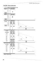
Page 30: ...DVA MINI Digital Array System 29 DVA MINI Quick configuration...

Page 31: ...disposition en angle d sir e ATTENZIONE Se il perno NON inserito all interno del blocco il diffusore NON bloccato ATTENTION If the pin is NOT inserted within the block the speaker is NOT locked ACHTUN...

Page 32: ...ATION DVA M2M DVA M2S KOMBINATION DVA M2M DVA M2S COMBINAISON DVA M2M DVA M2S La posizione dei due diffusori indicativa The position of the two speakers is indicative Die Position der beiden Lautsprec...

Page 33: ...32...

Page 34: ...gio dei diffusori The Red lever must be positioned as shown in the figure to ensure the locking of the speakers Der rote Hebel muss wie in Abbildung positioniert sein um die Blockierung der Lautsprech...

Page 35: ...34...

Page 36: ...DVA MINI Digital Array System 35 Selezionare l angolo di copertura desiderato Select the desired angle of coverage Den gew nschten Deckungswinkel ausw hlen S lectionner l angle de couverture d sir...

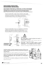
Page 37: ...precher aufgeh ngt werden und stack R p ter la m me s quence en cas de plusieurs diffuseurs en configuration suspendue en stack Bloccare la staffa con il pin in uno dei due fori indicati in figura Loc...

Page 38: ...Verf gung gestellt und damit verbundenen Sicherheitsanforderungen Nur Original Teile von dBTechnologies verwenden Falls unpassendes Zubeh r verwendet wird wird jegliche Haftung ausgeschlossen Alle Unt...

Page 39: ...qualifi qui doit veiller positionner un pied de support en direction du cot o sort le son c t ant rieur du diffuseur de mani re optimiser la stabilit par rapport au barycentre du diffuseur AVVERTENZA...

Page 40: ...re riferimento al manuale dedicato incluso nell accessorio For assembly instructions of the adapter and speakers refer to the included manual dedicated accessory ACCESSORIO RC M2 Protezione pioggia pe...

Page 41: ...40...

Page 42: ...DVA MINI Digital Array System 41...

Page 43: ...42...

Page 44: ...Array System A E B Industriale Srl Via Brodolini 8 Localit Crespellano 40053 VALSAMOGGIA BOLOGNA ITALIA Tel 39 051 969870 Fax 39 051 969725 www dbtechnologies com info dbtechnologies aeb com Codice 4...

Reviews: