background image


30 

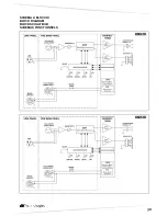
SCHEMA A BLOCCHI  
BLOCK DIAGRAM  
BLOCKSCHALTBILD  
SCHEMAS FONCTIONNELS 


 DM12TH  


 DM15TH   


Summary of Contents for DVX DM12TH

Page 1: ...servate congiuntamente al MANUALE D USO Sezione 2 The warnings in this manual must be observed together with the USER MANUAL Section 2 Die Warnungen in diesem Handbuch m ssen in Verbindung mit der BED...

Page 2: ...a destra o a sinistra Il doppio logo presente sul pannello permette di avere sempre visibile la posizione della tromba dall esterno della rete di protezione frontale La tromba a sua volta ruotabile L...

Page 3: ...Questo indicatore s illumina di colore verde per indicare che la tensione di alimentazione di rete corretta Nel normale funzionamento il led acceso 6 CONTROLLO SENSIBILITA INGRESSO INPUT SENS Questo...

Page 4: ...a alimentazione di rete Ogni diffusore attivo provvisto del proprio cavo di alimentazione Il collegamento avviene tramite un connettore modello Neutrik POWER CON blu che permette di avere una facile e...

Page 5: ...nnessione alla rete d alimentazione Assicurarsi della corretta tensione d alimentazione Controllare che l amplificatore non sia surriscaldato Scollegare dalla rete di alimentazione il diffusore attend...

Page 6: ...teriore svitare le otto viti di fissaggio della tromba ruotare la tromba nella posizione desiderata non estrarre mai il blocco tromba dal diffusore fissare nuovamente la tromba con le stesse viti ripo...

Page 7: ...50 60Hz con PFC Full Range 100 240 Vac 50 60Hz con PFC Corrente di accensione 16 1A 16 1A Consumo di corrente 100 120Vac 50 60Hz 220 240Vac 50 60Hz 10A 5A 10A 5A Dimensioni LxHxP 670x325x405 mm 26 4x1...

Page 8: ...or on the left The double logo on the panel allows to ensure that the horn position can always be seen from outside the front protection net The horn can be rotated in its turn The separation of the i...

Page 9: ...5 ON INDICATOR LED This indicator shows green to indicate that main power voltage is correct The LED is on in normal operating conditions 6 INPUT SENS INPUT SENSITIVITY CONTROL This control adjusts th...

Page 10: ...ker features its own power cable Connection is done by a Neutrik POWER CON blue model which permits easy and fast connection to the speaker as well as being an excellent locking system The same connec...

Page 11: ...elow Check if the speaker is properly connected to the mains supply Make sure that the power supply is of correct Check that the amplifier is not overheated Disconnect the speaker from the mains power...

Page 12: ...ight fixing screws of the horn rotate the horn in the desired position the horn should never be removed from the driver fix again the horn with the same screws removed before put the grille in its ori...

Page 13: ...Hz con PFC Full Range 100 240 Vac 50 60Hz con PFC Inrush current 16 1A 16 1A Current consumption 100 120Vac 50 60Hz 220 240Vac 50 60Hz 10A 5A 10A 5A Dimensions LxHxP 670x325x405 mm 26 4x12 8x15 9 inch...

Page 14: ...s doppelte Logo an der Frontplatte sorgt daf r dass die Position des Schalltrichters von au erhalb des frontalen Schutzgitters stets sichtbar ist Der Schalltrichter kann seinerseits ebenfalls gedreht...

Page 15: ...htige Netzspannung angeschlossen ist W hrend des normalen Betriebs leuchtet die LED 6 EMPFINDLICHKEITSREGLER EINGANG INPUT SENS Dieser Regler dient zum Einstellen der Eingangs Empfindlichkeit des Vers...

Page 16: ...u gew hrleisten ANSCHL SSE Netzanschluss Jeder Aktivlautsprecher hat ein eigenes Netzkabel Der Anschluss erfolgt mit einem Netzstecker Neutrik POWER CON blau der den einfachen und schnellen Anschluss...

Page 17: ...uss an das Stromnetz kontrollieren Sicher stellen dass die richtige Versorgungsspannung vorliegt Kontrollieren dass der Verst rker nicht berhitzt ist Den Lautsprecher vom Stromnetz trennen einige Minu...

Page 18: ...usdrehen das Horn in die gew nschte Richtung drehen den Treiber nicht vom Horn trennen die Befestigungsschrauben des Hornes wieder einschrauben das Frontgitter wieder einlegen und die Schrauben des Gi...

Page 19: ...60Hz con PFC Full Range 100 240 Vac 50 60Hz con PFC Einschaltstrom 16 1A 16 1A Stromverbrauch 100 120Vac 50 60Hz 220 240Vac 50 60Hz 10A 5A 10A 5A Abmessungen LxHxP 670x325x405 mm 26 4x12 8x15 9 inch...

Page 20: ...nt sur le panneau permet d avoir toujours visible la position du cornet de l ext rieur de la grille de protection frontale Le cornet peut son tour tre pivot La subdivision des connexions input output...

Page 21: ...EUX ON Cet indicateur s allume de couleur verte pour indiquer que la tension d alimentation de r seau est correcte Pendant le fonctionnement normal la LED est allum e 6 CONTR LE SENSIBILIT ENTR E INPU...

Page 22: ...u d alimentation Chaque enceinte active est dot e de son cordon d alimentation Le branchement s effectue au moyen d un connecteur mod le Neutrik POWER CON bleu qui rend ais et rapide le branchement de...

Page 23: ...orrect S assurer que la tension d alimentation soit correcte Contr ler que l amplificateur ne soit pas en surchauffe D brancher du r seau d alimentation le diffuseur et attendre quelques minutes et pu...

Page 24: ...visser les huit vis de fixation du c ne faire rouler le c ne dans la position d sir e ne jamais extraire le bloc c ne du diffuseur revisser les vis de fixation du c ne ins rer nouveau la protection et...

Page 25: ...Hz avec PFC Full Range 100 240 Vac 50 60Hz avec PFC Courant d appel 16 1A 16 1A Consommation de courant 100 120Vac 50 60Hz 220 240Vac 50 60Hz 10A 5A 10A 5A Dimensions WxHxD 670x325x405 mm 26 4x12 8x15...

Page 26: ...DVX DM TH Professional Stage Monitor 25 ROTAZIONE PANNELLO PANEL ROTATION DREHENDE PLATTEN PANNEAU TOURNANT...

Page 27: ...26 ANGOLO DI COPERTURA TROMBA HORN ANGLE COVERED HOCHTONHORN ABSTRAHLWINKEL ANGLE DE COUVERTURE COTE DM12TH...

Page 28: ...DVX DM TH Professional Stage Monitor 27 DM15TH...

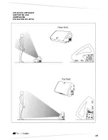
Page 29: ...28 UTILIZZO IN APPOGGIO SUPPORTED USE ANWENDUNG UTILISATION EN APPUI...

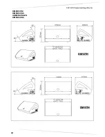
Page 30: ...DVX DM TH Professional Stage Monitor 29 DIMENSIONI DIMENSIONS ABMESSUNGEN DIMENSIONS DM12TH DM15TH...

Page 31: ...30 SCHEMA A BLOCCHI BLOCK DIAGRAM BLOCKSCHALTBILD SCHEMAS FONCTIONNELS DM12TH DM15TH...

Page 32: ...al Stage Monitor A E B Industriale Srl Via Brodolini 8 Localit Crespellano 40053 VALSAMOGGIA BOLOGNA ITALIA Tel 39 051 969870 Fax 39 051 969725 www dbtechnologies com info dbtechnologies aeb com Codic...

Reviews: