background image

4

INSTALLATION:

 To ensure effective installation of the Concrete Wedge Anchor, always observe the 

Installation 

Requirements

 defined in the previous section. Perform the following steps to install the Concrete Wedge Anchor. 

Refer to Figure 1 for component identification:

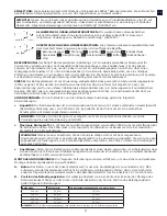
Step 1.

  Drill a 7.62 cm (3 in.) or deeper hole at the desired mounting location with a Rotary Hammer and 

industrial grade 20 mm (or 3/4 in.) Rotary Hammer Drill Bit.

WARNING:

 Before drilling holes, inspect the hole location to prevent drilling into power transmission 

cables or other live utilities.

Step 2.

  The mounting hole must be free of debris for the Concrete Wedge Anchor to develop maximum 

anchorage. Blow all debris out of the hole with a Blow-Out Bulb or Compressed Air. If you are reusing an 

existing hole, inspect thoroughly for debris and a uniform surface.

Step 3.

  Place your thumb in the anchor Swivel Ring (1A) and pull up on the Trigger (1C) with two fingers until 

fully retracted.

Step 4.

  Insert the anchor into the mounting hole until the Release Plug (1D) seats against the concrete surface 

and then release the Trigger (1C).

Step 5.

  Pull up on the anchor Swivel Ring (1A) to set the anchor.

REMOVAL:

 To release the Concrete Wedge Anchor, push down on the Release Plug (1D) and pull up on the 

Trigger (1C). If the anchor does not release, tap the Release Plug (1D) and repeat the process.

REUSE:

 The Concrete Wedge Anchor may be reused if it has not been subjected to a fall force.

DISPOSAL:

 Dispose of the Concrete Wedge Anchor if it has been subjected to fall force or 

Inspection

 reveals an 

unsafe or defective condition. Before disposing of the Concrete Wedge Anchor, cut the Wedges off the Retractor 

Cables (1J) to eliminate the possibility of inadvertent reuse.

INSPECTION FREQUENCY:

 To ensure safe, efficient operation, the Concrete Wedge Anchor should be inspected 

at the following intervals:

• 

Before Each Use: 

Visually inspect the Concrete Wedge Anchor per the 

Inspection

 steps defined in the next 

section.

• 

Annually:  

A formal inspection of the Concrete Wedge Anchor and its connection to the structure 

must be performed at least annually by a competent person other than the user. The frequency 

of formal inspections should be based on conditions of use or exposure. See the next section for 

Inspection

 steps. Record the inspection results in the 

Periodic Examination and Repair History

 in the 

“General Instructions for Use and Maintenance” (5902392)

.

IMPORTANT:

 Extreme working conditions (harsh environment, prolonged use, etc.) may require increasing the 

frequency of inspections.

INSPECTION:

 Per the intervals defined in in the previous section, inspect the Concrete Wedge Anchor as follows. 

(Refer to Figure 1 for component identification):

Step 1.

  Make sure the Concrete Wedge Anchor is straight and is operating smoothly.

Step 2.

  Make sure the Label (1B) is attached to the Concrete Anchor and is legible (see Figure 2).

Step 3.

  Make sure the Main Cable (1G) and Retractor Cables (1J) are not kinked, frayed, or damaged.

Step 4.

  Make sure metal components are not damaged or excessively corroded.

Step 5.

  Make sure the Wedges (1F) and Retractor Cables (1J) operate smoothly and no metal burrs are present. 

Ensure Wedges (1F) do not exhibit any deformities.

NOTE:

 Record the inspection date and results in the Periodic Examination and Repair History in the “General 

Instructions for Use and Maintenance” (5902392). If inspection reveals a defect, remove the anchor form 

service and dispose in the mannner indicated in the “Disposal” section.

CLEANING:

 After each use, blow off the Concrete Wedge Anchor with compressed air. Keep the anchor free of 

grease, oils, and dirt.

STORAGE:

 Store the Concrete Wedge Anchor in a clean dry environment. Avoid areas where chemical vapors 

may exist. Do not pile objects on top of the anchor. Thoroughly inspect the Concrete Wedge Anchor after extended 

storage.

SPECIFICATIONS:

 See the front cover for materials (Figure 1) and physical dimensions (Figure 3).

Summary of Contents for Saflok 2100100

Page 1: ...3 5 6 cm 7 6 cm 22 2 cm 10 2 cm 3 8 cm x1 49 5902392 48 3 1 Component 62 Material 18 G C D I E F H J B A A Swivel Ring 2 Zinc Covered Forged Steel 27 B Label 1 Vinyl 11 C Trigger 3 Aluminum 23 D Rele...

Page 2: ......

Page 3: ...EMENTS Installation and use of this equipment is restricted to the following limitations Capacity The Concrete Wedge Anchor is designed for use by persons with a combined weight clothing tools etc of...

Page 4: ...Before Each Use Visually inspect the Concrete Wedge Anchor per the Inspection steps defined in the next section Annually A formal inspection of the Concrete Wedge Anchor and its connection to the str...

Page 5: ...t de l utilisation de cet quipement Capacit Ce goujon d ancrage pour b ton est destin un usage par des personnes dont le poids total poids corporel v tements outils etc ne d passe pas 141 kg Un seul d...

Page 6: ...tion d finies dans la section suivante Chaque ann e Une inspection formelle du goujon d ancrage pour b ton doit tre effectu e au moins une fois par an par une personne comp tente autre que l utilisate...

Page 7: ...re di energia EN 355 un connettore EN 362 fissato al dispositivo di ancoraggio e un imbracatura per il corpo EN 361 REQUISITI l installazione e l utilizzo della presente attrezzatura sono soggetti all...

Page 8: ...ito Prima di ciascun utilizzo ispezionare visivamente il dispositivo di ancoraggio a cuneo in base ai passaggi di ispezione definiti nella sezione successiva Annualmente un ispezione formale del dispo...

Page 9: ...EN 361 ANFORDERUNGEN F r die Installation und den Einsatz dieser Ausr stung gelten die folgenden Einschr nkungen Kapazit t Der Betonspreizanker ist zur Verwendung durch Personen mit einem kombinierte...

Page 10: ...preizankers gem den im n chsten Abschnitt angegebenen Untersuchungsschritten durch J hrlich Der Betonspreizanker und sein Anschluss an die Struktur m ssen mindestens einmal j hrlich durch einen Sachve...

Page 11: ...360 o un acollador para absorci n de energ a EN 355 un conector EN 362 para fijarlo al anclaje y un arn s de cuerpo completo EN 361 REQUISITOS Este equipo tiene las siguientes limitaciones de instala...

Page 12: ...ia siguiente Antes de cada uso Inspeccione visualmente el anclaje en cu a para hormig n siguiendo los pasos definidos en la secci n Inspecci n siguiente ANUALMENTE Una persona experta distinta del usu...

Page 13: ...coragem e um arn s de corpo inteiro EN 361 REQUISITOS A instala o e uso deste equipamento est o condicionados pelas seguintes limita es Capacidade A ancoragem com cunha no bet o concebida para ser uti...

Page 14: ...e cada utiliza o Inspeccione visualmente a ancoragem com cunha no bet o de acordo com os passos da Inspec o definidos na pr xima sec o Anualmente necess rio realizar uma inspec o formal da ancoragem c...

Page 15: ...ringen samt en helkroppssele EN 361 KRAV Installation och anv ndning av denna utrustning begr nsas av f ljande inskr nkningar Kapacitet Betongkilf rankringen r konstruerad f r att anv ndas av personer...

Page 16: ...e intervall F re varje anv ndningstillf lle Inspektera betongkilf rankringen visuellt enligt inspektions tg rderna som definieras i n sta avsnitt rligen En formell inspektion av betongkilf rankringen...

Page 17: ...asennusta ja k ytt koskevat seuraavat rajoitukset Kapasiteetti Betonikiila ankkuri on suunniteltu k ytt n jossa sit k ytt vien henkil iden yhteispaino vaatetus ty kalut jne ei ylit 141 kg Vain yksi he...

Page 18: ...sta k ytt Tarkasta betonikiila ankkuri silm m r isesti seuraavassa osassa m ritettyjen tarkastusvaiheiden mukaisesti Vuosittain Betonikiila ankkuri ja sen kiinnitys rakenteeseen tulee tarkastaa virall...

Page 19: ...sorberende forbindelsesline EN 355 en ledning EN 362 for feste til ankeret samt en kroppssele EN 361 KRAV Montering og bruk av dette utstyret er innskrenket av f lgende begrensninger Kapasitet Concret...

Page 20: ...valler F r hver enkel bruk Inspiser betonganker med kile visuelt ved f lge trinnene i Inspisering som er definert i neste del rlig En formell inspisering av betonganker med kile og koblingene til stru...

Page 21: ...tallation og brug af udstyret er indskr nket af f lgende begr nsninger Kapacitet Kileankeret m kun anvendes af personer der har en kombineret v gt person bekl dning v rkt j osv p h jst 141 kg Der m ku...

Page 22: ...eankeret visuelt i overensstemmelse med trinene for Inspektion som er anf rt i n ste afsnit rligt Der skal udf res en formel inspektion af kileankeret og dets forbindelsesled mindst n gang om ret af e...

Page 23: ......

Page 24: ...CLAIMS ANY IMPLIED WARRANTIES OF MERCHANTABILITY OR FITNESS FOR A PARTICULAR PURPOSE AND SHALL NOT BE LIABLE FOR INCIDENTAL PUNITIVE OR CONSEQUENTIAL DAMAGES OF ANY NATURE INCLUDING WITHOUT LIMITATION...

Reviews: