background image

Summary of Contents for 165

Page 1: ... dbx Model 165 INSTRUCTION MANUAL l I I ...

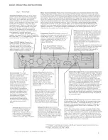
Page 2: ...ng harmonics that conventional clipping causes The level at which PeakStop is activated is adjustable from 2 to 24 dBm Note that small signal excursions above the set value of PeakStop are possible to allow the rounding to take place therefore for any applications where you must not exceed a given ceiling set the PeakStop control 1 2 dB below it to be sure The red PeakStop LED flashes whenever pea...

Page 3: ...Rate Release Rate Controls Where To Set Attack ReleaseControls Meter Cali bration Use Use of an Equalizer in the Level Detector Circuit for Frequency Weighted Compression De ess ing or Increasing Sustain Use of a Filt er in the Level Detector Circuit Use of a Time Delay Line in the Signal Path but not in the Level Detector Circuit for Zero or Negative Attack Release Times The 165 As A Line Amplifi...

Page 4: ...e channel monaural operation this switch determines whether the unit will be the master controlling unit or the slave The unit becomes a slave when the button is pressed IN and the LED above the button turns ON to indicate the slave status In stereo operation all gain attack release compression and threshold adjustments are made wit h the Master unit s controls The Slave follows the Master s comma...

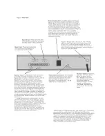
Page 5: ...nector to the Stereo Coup ler co nnector on anot her Mode l 165 and when one of the un its is switched to slave mode the two units may then be ut ilized for processin g a stereo program A multi pin male con nector is supplied with each 165 so the coupler cable can be assembled using the w iri ng diagram in Figure 7 NOT E On ly two Mode l 165 s can be coup led together Four units cannot be coup led...

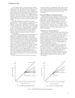
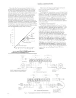
Page 6: ...sor 20 15 1o 10 O _J 5 UJ UJ _J 0 Cl 5 O 10 15 4 1 20 1 oo 1 Ro tat ion Point Th reshold 15 10 5 0 5 10 15 20 INPUT LEVEL d B 3A Con vention al Comp ressor Limiter limiter ever offered the dbx Model 165 is well suited t o a wide range of applicat ions incl uding tape record ing disc mastering radio and TV production and broadcast Iive concert sound reinfo rcement and theatrica l production More Ab...

Page 7: ...l Level Detector Input Connection For normal compressor operation leave the factory installed straps connected between the Detector and the Input Signal terminals and the Detector and Input Signal terminals Refer to Figure 5 If you wish to gain accessto the 165 s Detector Input for insertion of an auxiliary device you may do so by removing the strapping wiring the auxiliary device s output to the ...

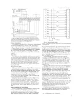
Page 8: ...anding regarding the nature of matching and bridging inputs the use of terminating resistors and the relationship between actual inp ut impedance and nominal source impedance Most electronic outputs work well when terminated 165STEREOCOUPLER CABLE 1 BLK RED 1 2 RED BLK 2 3 BLK WH 3 4 WH BLK 4 BLK 5 GN 5 GN 6 BLK 6 7 BLK BLU 7 8 BLU BLK 8 9 BLK BRN 9 10 RRN BLK 10 11 BLK BLK 11 12 YEL YEL 12 SHIELD...

Page 9: ...el sets the Model 165 for the same attack and releasecharacteristics as dbx Models 160 161 162 163 and 164 compressor 8 li miters When the Auto switch is OUT manual mode the LED indicator above it turns OFF and the front panel Attack and Releaserate controls determine the maximum rate of gain change and the behavior of the level detector ci rcuitry see below Attack Rate Release Rate Controls The M...

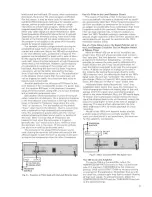
Page 10: ...ion than the other frequencies i INPUT OUTPUT FILTER OR EQUA LIZER PROGRAM SOURCE t _ 0 Fig 8 Equalizer or Filter Used with the Level Detector Input Use of a Filter in the Level Detector Circuit The results of inserting a filter in the level detector circuit are basically the same as obtained with an equali zer as previously described Those frequencies passedby the filter are subject to compressio...

Page 11: ...vel or gain change CALIBRATION Factor y preset at O VU 4 dB 1 23 V rear panel potentiometer sets O VU for any level from 1 0 dB 7 8 mVI to 10 dB 2 45 V Connectors SIGNAL Jones type barrier strip for signal input signal output and detector input STEREO COUPLER 12 p in Cinch Jones J 312 CCT connector for stra pp ing two 165 s toget her to process a stereo program General POWER REQUIREMENTS 117 V AC ...

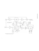
Page 12: ...tail Meter Inputs are 1101 shown in full detai l Voltage Controlled Amplifier Out Slave Master 1 l From To J r Stereo Interconnect Stereo 1 Det ector 1 2 RMSI 2 Smal l Cap I J I 2 I t Manua l Automati c j Large Cap L Threshold Compression Ratio Output Gain i Bypass Normal J t Signal Output Single Endedl Differentia l in Bypass Threshold Lights Automatic Manual In Time Constant Generator Attack Rel...

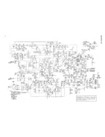
Page 13: ...lA I L t 7 R 1 ll TlltGO Ntrr II 5 s V AUTO 1 MAST TROL 0 1 f H 14 241 J 91 ISV R l 4 S IOK l f I R S YM Rt50 fl c 1 eJ10 N l K f5V SV RGS 3 llK OAI lK f C t R O 3 I 8 5 t CO l i rlr t 4 RS 4 __ _ 1 r JO 5 y i soo 1 s s r NV c L I co Zl J M S 1 1 2 C 53 z r r _ 516 pp sv w Rstmts sv R 147 V 4 CA 3V 45 2 L so c lntACM a U K C51 cw i f s r v H f _ _ _ J O 1 18 Od o i t V Cl OMV sv 5 TA CK7 l U t 1 1...

Page 14: ...s are synchronized However the bias energy level has a direct effect on the recorded level background noise and the distortion It is sometimes necessary to reset the bias level for optimum performance with different types of record ing tape and professional tape mach ines are equipped w it h continu ously variable bias controls many consumer tape machines are now equipped w ith bias selector switc...

Page 15: ...hat program the circuit may be said II to encode the program The equipment or circuit which performs this function is known as an encoder Encoded programs must decoded only with complementary decoding circuitry Typical encoded programs include FM multiplex broadcasts matrix quadraphonic recordings and dbx encoded recordings Envelope In music the envelope of a note describes the change in average s...

Page 16: ...nals vary depending on the audio system H1 F1line levels are nom nally 15dBV whereas professiona l l ne levels are nominal ly 4dBm or 8d8m wi th typical dynam cs ranging from 50d8m 10 24d8m Line nputs are simply inputs that have sensitivi ties nten ded for line level preamplified signals Often the nominal impedance of a line leve l inpu t will be different than the nom inal impedance of a mic leve...

Page 17: ...essed as the tracking accuracy of the controls T he level detection circuitry in a dbx encoder sensesthe signal level changes the gain and creates an encoded signal The corre sponding sameness of the original signal and the encoded decoded signal can be expressed as the tracking accurac y of the noise reduction system dbx systems are non critical for the operator and are built to close tolerances ...

Reviews: