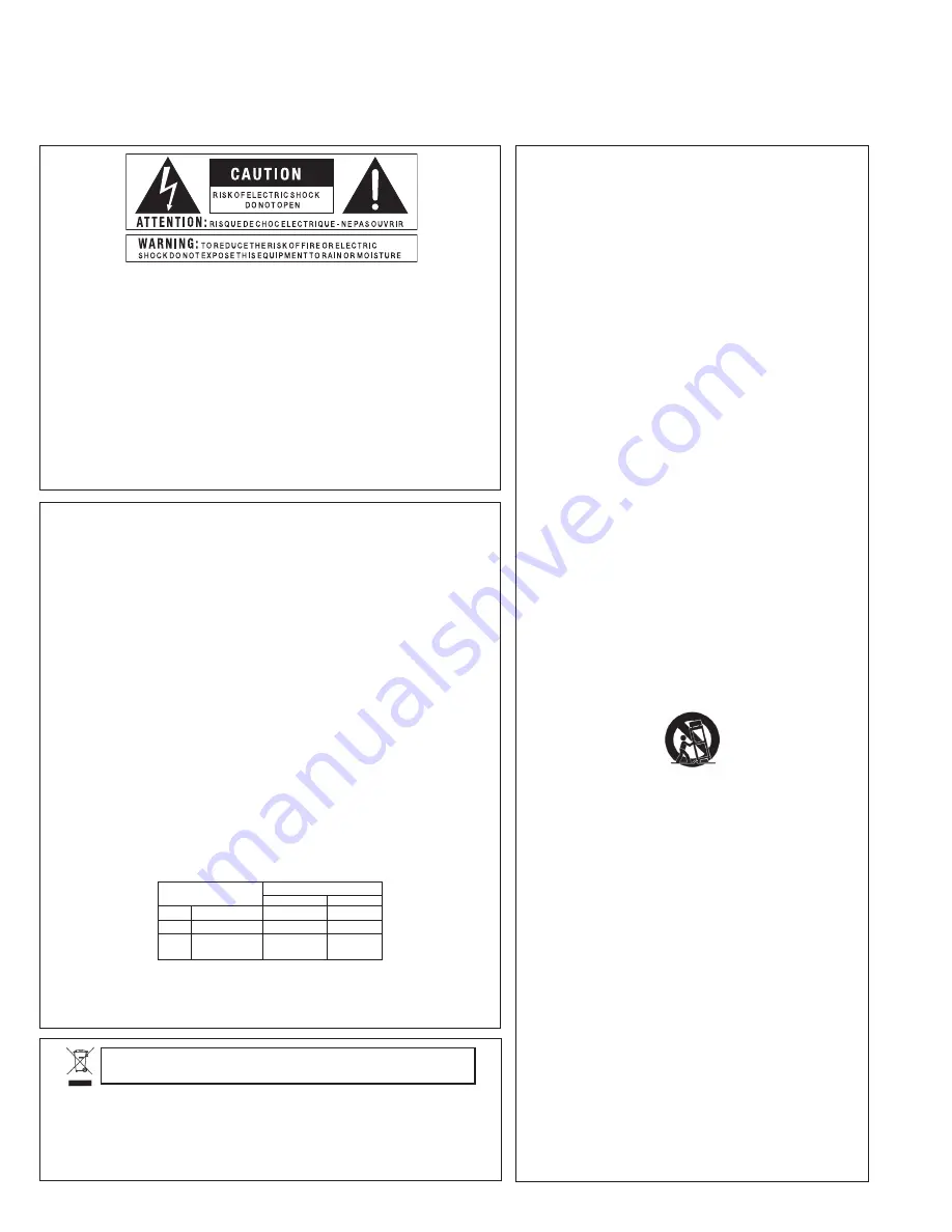
IMPORTANT SAFETY INFORMATION
WARNING FOR YOUR PROTECTION
READ THE FOLLOWING:
KEEP THESE INSTRUCTIONS
HEED ALL WARNINGS
FOLLOW ALL INSTRUCTIONS
THE APPARATUS SHALL NOT bE ExPOSED TO DRIPPING OR
SPLASHING LIqUID AND NO ObjECT FILLED WITH LIqUID,
SUCH AS vASES, SHALL bE PLACED ON THE APPARATUS.
CLEAN ONLY WITH A DRY CLOTH.
DO NOT bLOCK ANY OF THE vENTILATION OPENINGS.
INSTALL IN ACCORDANCE WITH THE MANUFACTURER’S
INSTRUCTIONS.
DO NOT INSTALL NEAR ANY HEAT SOURCES SUCH AS RA-
DIATORS, HEAT REGISTERS, STOvES, OR OTHER APPARATUS
(INCLUDING AMPLIFIERS) THAT PRODUCE HEAT.
ONLY USE ATTACHMENTS/ACCESSORIES SPECIFIED bY THE
MANUFACTURER.
UNPLUG THIS APPARATUS DURING LIGHTNING STORMS OR
WHEN UNUSED FOR LONG PERIODS OF TIME.
Do not defeat the safety purpose of the polarized or grounding-
type plug. A polarized plug has two blades with one wider than the
other. A grounding type plug has two blades and a third grounding
prong. The wide blade or third prong are provided for your safety.
If the provided plug does not fit your outlet, consult an electrician
for replacement of the obsolete outlet.
Protect the power cord from being walked on or pinched particu-
larly at plugs, convenience receptacles, and the point where they
exit from the apparatus.
Use only with the cart stand, tripod bracket, or table specified by
the manufacture, or sold with the apparatus. When a cart is used,
use caution when moving the cart/apparatus combination to avoid
injury from tip-over.
Refer all servicing to qualified service personnel. Servicing is
required when the apparatus has been damaged in any way, such
as power-supply cord or plug is damaged, liquid has been spilled
or objects have fallen into the apparatus, the apparatus has been
exposed to rain or moisture, does not operate normally, or has
been dropped.
POWER ON/OFF SWITCH: If the equipment has a Power switch,
the Power switch used in this piece of equipment DOES NOT
break the connection from the mains.
MAINS DISCONNECT: The plug shall remain readily operable.
For rack-mount or installation where plug is not accessible, an
all-pole mains switch with a contact separation of at least 3 mm in
each pole shall be incorporated into the electrical installation of the
rack or building.
FOR UNITS EqUIPPED WITH ExTERNALLY ACCESSIbLE FUSE
RECEPTACLE: Replace fuse with same type and rating only.
MULTIPLE-INPUT vOLTAGE: This equipment may require the use
of a different line cord, attachment plug, or both, depending on the
available power source at installation. Connect this equipment only
to the power source indicated on the equipment rear panel. To
reduce the risk of fire or electric shock, refer servicing to qualified
service personnel or equivalent.
If connected to 240v supply, a suitable CSA/UL certified power
cord shall be used for this supply.
Safety InStructIonS
Notice For customers iF Your uNit is equipped With A poWer cord.
WArNiNG: this AppLiANce shALL Be coNNected to A mAiNs socKet outLet With A protectiVe eArthiNG
coNNectioN.
the cores in the mains lead are coloured in accordance with the following code:
GREEN and YELLOW - Earth BLUE - Neutral BROWN - Live
As colours of the cores in the mains lead of this appliance may not correspond with the coloured markings
identifying the terminals in your plug, proceed as follows:
• the core which is coloured green and yellow must be connected to the terminal in the plug marked with the
letter e, or with the earth symbol, or coloured green, or green and yellow.
• the core which is coloured blue must be connected to the terminal marked N or coloured black.
• the core which is coloured brown must be connected to the terminal marked L or coloured red.
this equipment may require the use of a different line cord, attachment plug, or both, depending on the
available power source at installation. if the attachment plug needs to be changed, refer servicing to qualified
service personnel who should refer to the table below. the green/yellow wire shall be connected directly to
the units chassis.
CONDUCTOR
WIRE COLOR
Normal
Alt
L
LIVE
BROWN
BLACK
N
NEUTRAL
BLUE
WHITE
E
EARTH GND
GREEN/
YEL
GREEN
WARNING:
if the ground is defeated, certain fault conditions in the unit or in the system to which it is connected
can result in full line voltage between chassis and earth ground. severe injury or death can then result if the
chassis and earth ground are touched simultaneously.
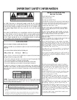
the symbols shown above are internationally accepted symbols that warn of potential
hazards with electrical products. the lightning flash with arrowpoint in an equilateral triangle
means that there are dangerous voltages present within the unit. the exclamation point
in an equilateral triangle indicates that it is necessary for the user to refer to the owner’s
manual.
these symbols warn that there are no user serviceable parts inside the unit. do not open the
unit. do not attempt to service the unit yourself. refer all servicing to qualified personnel.
opening the chassis for any reason will void the manufacturer’s warranty. do not get the
unit wet. if liquid is spilled on the unit, shut it off immediately and take it to a dealer for
service. disconnect the unit during storms to prevent damage.
If you want to dispose this product, do not mix it with general household waste. There is a
separate collection system for used electronic products in accordance with legislation that
requires proper treatment, recovery and recycling.
Private household in the 25 member states of the EU, in Switzerland and Norway may return their used
electronic products free of charge to designated collection facilities or to a retailer (if you purchase a similar
new one).
For Countries not mentioned above, please contact your local authorities for a correct method of disposal.
By doing so you will ensure that your disposed product undergoes the necessary treatment, recovery and
recycling and thus prevent potential negative effects on the environment and human health.


