background image

®

AES/EBU Digital Connector

The 386 provides AES/EBU digital output formating through the XLR connector. Be sure to use short
lengths of 110

digital cables rather than standard XLR to XLR cables. Using the correct cables will pre-

vent digital dropouts and other interconnection problems.

S/PDIF Digital Connector 

The 386 provides S/PDIF digital output formating through the RCA coaxial connector. Be sure to use
short lengths of 75

digital cables or 75

video cables rather than standard audio RCA to RCA cables.

Using the correct cables will prevent digital dropouts and other interconnection problems.

NOTE: Although digital information is coming out of both XLR and RCA jacks simultaneously, the correct format will only appear at
the output for the format type selected.  For example, if you have AES/EBU format selected, an AES/EBU formatted signal will appear
at the output of both the XLR and the RCA connector.  Or, if you have S/PDIF format selected, an S/PDIF formatted signal will appear
at the output of both the RCA and XLR connectors.

Sync In and Out Connectors

BNC connectors are provided for both word clock in and out functions. The 386’s clock chips are
dbx custom VCXO chips, designed for low-jitter performance.  You may use the 386 as a master
clock source, having other equipment slave to the 386, or you may slave the 386’s clock to any
other word clock source. 

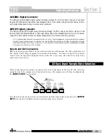
When connecting an incoming or master device to the sync input of the 386, the 386 will auto-
matically lock to the sample rate of the master device. The sample rate will then be indicated in
the 

SAMPLE RATE

select button.  

Note that when the master device is disconnected from the Sync Input connection, the 

SAMPLE

RATE

select button will flash until an internal sample rate is selected.

3.3 Sync Input Sample Rate Selection

Digital Applications

Section 3

386

11

386 User Manual

Summary of Contents for 386

Page 1: ... 386 Dual Vacuum Tube Preamp w Digital Out User Manual ...

Page 2: ...ores in the mains lead are coloured in accordance with the following code GREEN and YELLOW Earth BLUE Neutral BROWN Live As colours of the cores in the mains lead of this appliance may not correspond with the coloured markings identifying the terminals in your plug proceed as follows The core which is coloured green and yellow must be connected to the ter minal in the plug marked with the letter E...

Page 3: ...ä käytetty paristo valmistajan ohjeiden mukaisesti VARNING Explosionsfara vid felaktigt batteribyte Använd samma batteri typ eller en ekvivalent typ som rekommenderas av apparattil lverkaren Kassera använt batteri enligt fabrikantens instruk tion IMPORTANT SAFETY INSTRUCTIONS ELECTROMAGNETIC COMPATIBILITY This unit conforms to the Product Specifications noted on the Declaration of Conformity Opera...

Page 4: ...2 3 Direct Connection to a Recorder 7 Section 3 Digital Applications 3 1 Digital Output Front Panel Functions 10 3 2 Digital Rear Panel Connections 10 3 3 Sync Input Sample Rate Selection 11 3 4 Direct Connection to a DAW CPU 12 3 5 Direct Connection to a Digital Mixer 13 3 6 A D Conversion 14 3 7 Multi Tracking to Digital 15 3 8 Analog and Digital Output Applications 16 Appendix Sync Input Info 1...

Page 5: ...INTRO CUSTOMER SERVICE INFO 386 DEFINED WARRANTY INFO INTRODUCTION 386 ...

Page 6: ...e preamp capabilities in the analog domain as well as giving you pristine digital output capabil ities Listed below are some of features available to you in the 386 Two channel tube microphone pre amplifier 200V Tube Plate Voltage Insert Jack 60 dB of microphone gain and 15 dB of output gain Selectable mic line switch 48 volt phantom power 20 dB pad 75 Hz low cut filter Phase reverse 12 segment LE...

Page 7: ...d not collect Do not ship parcel post This warranty is valid only for the original purchaser and only in the United States 1 The warranty registration card that accompanies this product must be mailed within 30 days after purchase date to validate this warranty Proof of purchase is considered to be the bur den of the consumer 2 dbx warrants this product when bought and used solely within the U S t...

Page 8: ...meter at the top and one centimeter at the bottom of the unit to allow prop er ventilation The 386 should not be mounted above or below anything that generates exces sive heat Ambient temperatures should not exceed 1130 F 450 C when equipment is in use Although the unit is shielded against radio frequency and electromagnetic interference extreme ly high fields of RF and EMI should be avoided where...

Page 9: ...Getting Started Getting Started Section 1 386 ...

Page 10: ...at selected an S PDIF formatted signal will appear at the output of both the RCA and XLR connectors Sync In and Out Connectors BNC connectors are provided for both clock in and out functions The 386 s clock chips are dbx custom VCXO chips designed for low jitter performance You may use the 386 as a master clock source having other equipment slave to the 386 or you may slave the 386 s clock to any ...

Page 11: ...enser microphones on pins 2 and 3 of the XLR mic input You should connect your microphone before turning on the phantom power to pre vent damage to your microphone Be sure to always lower levels prior to using the the 48 Volt Switch 20db Pad Switch This switch attenuates the microphone input signal by 20dB Phase Switch This switch inverts the phase of the incoming signal at the Mic input by swappi...

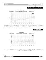
Page 12: ...dither algorithm When the LED is off dithering is not in use Shape Switch This switch selects either the Shape 1 or Shape 2 psycho acoustic noise shaping curve Shape 1 utilizes a mild psycho acoustic curve while the curve used in Shape 2 tends to be more aggressive Please see the Noise Shaping graph in section D 1 of the Appendix The LED will light GREEN for Shape 1 and RED for Shape 2 When the LE...

Page 13: ...ANALOG APPLICATIONS ANALOG APPLICATIONS Section 2 386 ...

Page 14: ...ected to the 386 Apply power to the 386 Connect the AC power cord to the AC power receptacle on the back of the unit Route the AC power cord to a convenient power outlet away from audio lines The unit may be turned on and off from the rear panel power switch or from a master equip ment power switch 1 Connect your mic cable to the Mic input of the 386 NOTE If you are using a mic with a separate pow...

Page 15: ...f the specific track of the recorder and open the specific tape track return in the console which corresponds to the track to which the 386 is connected As you increase the setting of the DRIVE control you should begin to hear the input of the 386 running through the recorder and returning to your console as a tape return 2 3 Direct Connection to a Recorder Analog Applications Section 2 386 386 Us...

Page 16: ......

Page 17: ...DIGITAL APPLICATIONS DIGITAL APPLICATIONS Section 3 386 ...

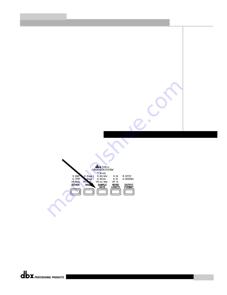
Page 18: ...d in Shape 2 tends to be more aggres sive Please see the Noise Shaping graph in section D 1 of the appendix The LED will be lit GREEN for Shape 1 and RED for Shape 2 When the LED is off the noise shaping algorithm is not in use Sample Rate Switch This switch selects the digital output sample rate of either 44 1 48 88 2 or 96 kHz The LED will not be lit for 44 1 kHz GREEN for 48 kHz RED for 88 2 kH...

Page 19: ...n AES EBU formatted signal will appear at the output of both the XLR and the RCA connector Or if you have S PDIF format selected an S PDIF formatted signal will appear at the output of both the RCA and XLR connectors Sync In and Out Connectors BNC connectors are provided for both word clock in and out functions The 386 s clock chips are dbx custom VCXO chips designed for low jitter performance You...

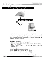
Page 20: ...atures 1 Use the METER switch to select digital output metering 2 Use the DITHER switch to select the desired dither algorithm 3 Use the SHAPE switch to select the desired noise shaping algorithm 4 Use the SAMPLE RATE switch to select the correct sampling rate 5 Use the WORD LENGTH switch to select the correct word length 6 Use the OUTPUT FORMAT switch to select the appropriate digital output form...

Page 21: ... RATIO 4 1 1 10 1 6 1 1 1 2 1 3 1 PeakStopPlus OUTPUT GAIN THRESHOLD 0 20 10 10 20 dB SC Enable SC Mon OverEasy Contour Auto I O Meter Bypass Stereo Couple EXPANDER GATE LIMITER COMPRESSOR GAIN REDUCTION dB INPUT OUTPUT LEVEL dBu THRESHOLD THRESHOLD THRESHOLD SC Enable SC Mon OverEasy Contour Auto I O Meter Bypass RATIO RELEASE 24 18 12 6 0 6 12 18 24 18 12 6 0 6 12 18 24 21 27 30 18 15 12 9 6 4 2...

Page 22: ... Features 1 Use the METER switch to select digital output metering 2 Use the DITHER switch to select the desired dither algorithm 3 Use the SHAPE switch to select the desired noise shaping algorithm 4 Use the SAMPLE RATE switch to select the correct sampling rate 5 Use the WORD LENGTH switch to select the correct word length 6 Use the OUTPUT FORMAT switch to select the appropriate digital output f...

Page 23: ...al output metering 2 Use the DITHER switch to select the desired dither algorithm 3 Use the SHAPE switch to select the desired noise shaping algorithm 4 Use the SAMPLE RATE switch to select the correct sampling rate 5 Use the WORD LENGTH switch to select the correct word length 6 Use the OUTPUT FORMAT switch to select the appropriate digital output format 24 24 SYNC AES EBU or S PDIF 3 7 Multi Tra...

Page 24: ...source to the desired 1 4 TRS or XLR input Connect the AES EBU or S PDIF output of the 386 and run into the AES EBU or S PDIF input interface of the DAW CPU Connect the 1 4 TRS or XLR output of the 386 and run into the 1 4 TRS or XLR input of the monitoring device Front Panel Digital Output Features 1 Use the METER switch to select digital output metering 2 Use the DITHER switch to select the desi...

Page 25: ...APPENDIX SyncInputInfo BlockDiagram dbxTypeIV WhitePaper Noise ShapingAlgorithms Truncation Specifications APPENDIX Appendix 386 ...

Page 26: ...ed marked 75 ohm terminated on the circuit board Unfortunately some equipment does not allow the user to change the termination setting These pieces of equipment are usually provided with a per manent termination If you use the 386 with another piece of terminated equipment in tapped configuration you should unterminate marked unterminated on the circuit board the 386 s sync input The same is true...

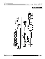
Page 27: ...Output Format Shape Peak LED Line Mic 12AU7 Tube Drive Analog Output Level Analog Outputs Digital Output Level Rear Panel Line Input Front Panel Instrument Input Bargraph Meter Analog Digital Insert dbx Pulsar Chip Word In Word Out S PDIF Output AES EBU Output Block Diagram Block Diagram Appendix B 386 19 386 User Manual ...

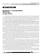
Page 28: ...g and jumped on the dig ital bandwagon were either never aware of or simply took for granted Anyone who has ever used analog tape knows that you can hit it hard without destroying the recording The printed specifications of analog tape don t take into account the practical headroom available The max signal to noise specification of analog tape is measured by defining the max signal as the point wh...

Page 29: ...s that Type IV improves the performance of any A D converter from low cost 16 bit to high perfor mance 24 bit And no decoding is necessary beyond the conversion process As we have previously mentioned digital systems have a wide linear region compared to analog tape and the dynamic range of A D converters has improved significantly in recent years The dbx Type IV Conversion System takes advantage ...

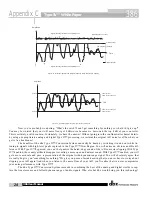
Page 30: ...n afforded by this density of digital codes to represent more input dynamic range in this region Another advantage of the logarithmic mapping of our dbx Type IV Conversion System is that it preserves the high frequency detail of the signal in the overload region Figs 3a through 3d illustrate what happens when you over load an A D converter without Type IV Fig 3a shows an input signal having both l...

Page 31: ...gnal of Fig 3a Going Beyond the A D Clip Level Amplitude Time A D Clip Level A D Clip Level Figure 3a Signal Having Low and High Frequency Content Amplitude Time Type IV White Paper Appendix C 386 23 386 User Manual ...

Page 32: ... more open and natural sound With Type IV enabled you will get a more accurate and pure representation of the original wide dynamic range signal You will absolutely agree that we really do give you something for nothing We give you peace of mind knowing that you never have to worry about clipping your A D again And when you listen to the noise floor of your A D you ll realize that we never comprom...

Page 33: ...kHz FFT Length 2048 Sample Rate 48 Khz Averages 32 Graph Steps 1024 a 24 Bit word b 16 Bit truncated output no dither Parameters Input 60dBFS 1 kHz FFT Length 2048 Sample Rate 48 Khz Averages 32 Graph Steps 1024 D 2 D 2 Truncation D 1 D 1 Noise Shaping Algorithms Appendix Appendix D 386 25 386 User Manual ...

Page 34: ...Input Output Connectors BNC Input Impedance 75Ω terminated by internal jumper Input 96 88 2 48 or 44 1kHz word clock Output 96 88 2 48 or 44 1kHz word clock System Performance DRIVE Control Range 30dB to 60dB for Mic Input 15dB to 15dB for Line and Instrument Inputs LEVEL Control Range Analog and Digital 15dB to 15dB LINE Selects between microphone and line inputs Phantom Power 48V PAD 20dB pad PH...

Page 35: ...andy Utah 84070 Phone 801 568 7660 Fax 801 568 7662 Int l Fax 603 672 4246 Questions or comments E mail us at customer dbxpro com or visit our World Wide Web home page at www dbxpro com A Harman International Company 18 0098 A ...

Reviews: