Rear Panel: Preamp
WIRING SCHEME
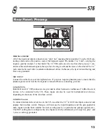
All of the input and output connectors are Òpin 2 hotÓ meaning that pin number 2 on the XLR con-
necting cables carries the positive side of the balanced signal. Pin number 3 is ÒcoldÓ, carrying the
negative polarity and pin 1 is the shield. The 1/4Ó TRS jacks are wired so that when you use 3 con-
ductor cables and balanced signals, the tip is hot, the ring is cold and the sleeve is the shield. The 1/4Ó
jacks can also be used with 2 conductor unbalanced cables. In this case, the tip is hot and the ring and
sleeve are grounded.
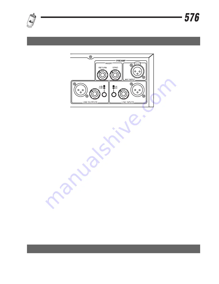
MIC INPUT
Connect the cable from your microphone here. If your mic requires phantom power, ensure that the
phantom power switch on the front panel is turned off before connecting your mic.
LINE INPUTS
Both XLR and 1/4Ó TRS connectors are provided to allow balanced or unba4 dBu line-level
devices to be connected to the 576. These inputs can also be used for instrument-level devices,
depending on the status of the Line/Inst. switch.
LINE/INST switch
To connect instrument-level devices to the 576, use either the 1/4Ó or XLR Line Input connector and
depress the Line/Inst. switch. Doing so will increase the input impedance and the gain applied to
these inputs to make them suitable for devices using passive or piezoelectric pickups (guitars etc.).
The INST. setting also reconfigures the Line Inputs as strictly unbalanced, pin 2 (tip) hot, pins 1 and
3 (sleeve and ring) grounded.
13


