Preamp Controls (cont.)
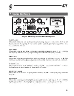
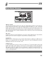
EQ switch
This switch enables the equalizer. When the equalizer is disabled, the EQ circuit is hardwire
bypassed. This switch allows you to instantly assess the effect of your EQ settings.
PEAK led
This red led illuminates when the 576Õs internal signal level is within 3 dB of clipping. The signal
level is monitored at all critical stages of the circuit.
LINE switch
When activated, this switch selects the rear-panel line inputs as the source signal to the preamp. When
this switch is de-activated, the mic input is the source to the preamp.
DRIVE control
This control sets the amount of gain that will be applied at the input of the vacuum tube stage. The
range of gain available is +10 to +60 dB. The Drive control works in conjunction with the Level con-
trol to determine the degree of tube saturation to be applied to the signal. For minimal tube saturation
(cleanest possible sound), use relatively low settings of the Drive control and higher settings of the
Level control. Moderate amounts of tube character can be achieved with moderate settings of the
Drive and Level controls; if a high degree of tube saturation is desired, this result can be obtained by
using higher settings of the Drive control in conjunction with lower settings of the Level control.
Experiment with different settings of the Drive and Level controls to find the amount of tube satura-
tion that is right for you.
+48V switch
This switch activates phantom power for condenser microphones on pins 2 and 3 of the XLR mic
input. You should connect your microphone before turning on the phantom power to prevent high
voltage arcing that may damage your mic.
20dB PAD switch
This switch inserts a 20 dB attenuator circuit into the signal path from the microphone input. The pad
is inserted before the signal is routed through the mic preamp gain stage. Use the 20 dB Pad to atten-
uate signals from ÒhotÓ sources such as high-output microphones.
INVERT switch
This switch inverts the phase of the incoming signal at the Mic input by swapping pins 2 and 3 on
the XLR connector. Phase inversion is typically used to overcome Ònotchy-soundingÓ comb filtering
effects when using multiple mics on a single source. It can also be used when the audio cable from
the source device has been wired to another pin arrangement.
6

