background image

Note: 

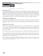
T

he shorting link between chassis ground and signal ground should be left installed, unless another

grounding scheme is used.

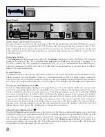
1/4 Inch Anchor Bolt

We have provided a 1/4” anchor bolt on the rear panel of the 786 to aid in securing the unit in your
rack. Since the 786 is a heavy unit, we recommend securing the 786 to a rear rack rail to avoid unnec-
essary stress on the front panel and front rack rails of your rack. The anchor bolt provides no electrical
or audio benefit to the 786, and no grounding or electrical wires should be connected to it.

AC Power Switch

Located beside the 

AC Power

connector, the 

AC Power

switch turns the 786 ON and OFF. When the

switch is in the DOWN position, revealing the red portion of the switch, the AC power to the 786 is ON.
When the switch is in the UP position, no AC power is being supplied to the 786, regardless of other
power connections.

AC Power Connector

The 

AC Power

connector is a standard IEC 320 power inlet receptacle, for use with any IEC-type power

cord (included with the 786). Connect this cable to any 50Hz or 60Hz AC power source of the correct
line voltage for your area. Make sure this voltage is also correct for the voltage marked on the back of
the 786. Always make AC power connections with the AC power switch in the OFF position (see above).
The 786 consumes a maximum power of 50 watts.

Warning:

Be sure to verify both your actual line voltage and the voltage for which your 786 is wired, as indi-
cated on the back panel of the unit. Connection to an inappropriate power source may result in exten-

9

controls

Operating

786

2

1

3

Jensen

¨


Output 

Transformer

Jensen

¨


Output 

Transformer

10k 1W

GND

Switch

GND

Switch

BALANCED FLOATING OPERATION

UNBALANCED FLOATING OPERATION

Chassis

Ground

Chassis

Ground

Chassis

Ground

Ground Switch open

Unbalance Switch open

Ground Switch open

Unbalanced Switch closed

(6dB drop in output level)

Jensen

¨


Output 

Transformer

Jensen

¨


Output 

Transformer

10k 1W

GND

Switch

GND

Switch

BALANCED GROUND-

REFERENCED OPERATION

UNBALANCED GROUND-

REFERENCED OPERATION

Chassis

Ground

Chassis

Ground

Ground Switch closed

Unbalance Switch open

Ground Switch closed

Unbalance Switch closed

(6dB drop in output level)

+

-

+

-

+

-

+

-

2

1

3

Chassis

Ground

2

1

3

Chassis

Ground

2

1

3

Chassis

Ground

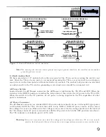
Figure 5

: Ground/Unbalance switch operation.

Summary of Contents for 786

Page 1: ...Precision Mic Preamp 786 Owner s Manual...

Page 2: ...t or in the system to which it is connected can result in full line voltage between chassis and earth ground Severe injury or death can then result if the chassis and earth ground are touched simultan...

Page 3: ...nsole Signal Path 3 Connection To Your System 4 Operating Controls 6 Front Panel Description 6 Rear Panel Description 8 Technical Support Factory Service 10 Warranty 11 Specifications 11 Block Diagram...

Page 4: ...in mind We wanted to create a pristine mic pre that would carefully reveal the very subtle nuances of any source device To that end the 786 uses premium parts and as short a signal path as possible t...

Page 5: ...t upon the signal EQ dynamics panning etc Unfortunately console preamp circuits are often not given enough room on the circuit board or high quality parts It is for this reason that outboard pre amps...

Page 6: ...red settings including phantom power and Low Z Connect the audio output of the 786 to the console s LINE INPUT and ensure that the con sole s input selection switch is set to LINE and the console s ga...

Page 7: ...a compressor limiter in the path before the recorder The perfect com panion product to the 786 is the dbx 160SL Stereo Compressor Also when recording with this method remember that desired gain change...

Page 8: ...rated to the frequency at which 3dB of boost or cut occurs when the Detail con trol is set at 16dB or 16dB respectively Detail Control This control adjusts the amount of boost or cut of the high frequ...

Page 9: ...or consistent performance 20dB Pad Switch and LED This switch inserts a 20dB attenuator circuit into the signal path from the microphone input The pad is inserted before the signal is routed through t...

Page 10: ...ssis Ground Binding Post The green Chassis Ground binding post is supplied to give the user another method to provide com prehensive grounding options for any installation It is easy to think of the b...

Page 11: ...e to any 50Hz or 60Hz AC power source of the correct line voltage for your area Make sure this voltage is also correct for the voltage marked on the back of the 786 Always make AC power connections wi...

Page 12: ...registration card and send it in please do so now Before you return a product to the factory for service we recommend you refer to the manual Make sure you have correctly followed installation steps...

Page 13: ...y obligation or liability in connection with the sale of this product In no event shall dbx or its dealers be liable for special or consequential damages or from any delay in the perfor mance of this...

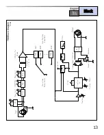
Page 14: ...low LED to indicated when 12 dB octave mode is selected Peak Red LED to indicated when signal is within 3 dB of clipping Sense points are out put of M8 gain module Course Gain output of Fine Control a...

Page 15: ...in Switching Relay Bank Coarse Gain Rotary Switch 15dB 20dB 65dB M8 Mic Pre Module 48V Relay Relay Super Low Z 20dB Pad Phase Invert Relay Relay Relay Relay Rectifier Unbalance Ground Spectrum Detail...

Page 16: ...Utah 84070 Phone 801 568 7660 Fax 801 568 7662 Int l Fax 603 672 4246 Questions or comments E mail us at customer dbxpro com or visit our World Wide Web home page at www dbxpro com A Harman Internatio...

Reviews: