AFS2 Quick Start Guide
PN: 5040506-B
CONNECTED TO MIXER BUS INSERTS
Left Main
Powered Speaker
Right Main
Powered Speaker
Mixer
Bus 1
Insert
Bus 2
Insert
L Main
Out
R Main
Out
To Power
Outlet
Insert Cable
Insert Cable
Send
Return
Send
Return
CONNECTED IN-LINE BETWEEN MIXER AND AMPS
Left Main
Powered Speaker
Right Main
Powered Speaker
Mixer
L Main
Out
R Main
Out
To Power
Outlet
CONNECTED TO MIXER CHANNEL INSERTS
Left Main
Powered Speaker
Right Main
Powered Speaker
Mixer
Ch. 1
Insert
Ch. 2
Insert
L Main
Out
R Main
Out
To Power
Outlet
Insert Cable
Insert Cable
Send
Return
Send
Return
CONNECTED TO MIXER MASTER INSERTS
Left Main
Powered Speaker
Right Main
Powered Speaker
Mixer
R Main
Insert
L Main
Insert
L Main
Out
R Main
Out
To Power
Outlet
Insert Cable
Insert Cable
Send
Return
Send
Return
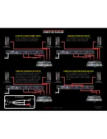
Use this configuration to independently protect
two single microphones from feedback, while
leaving all other audio channels unaffected.
Use this configuration to protect two independent
groups of microphones from feedback, while
leaving all other audio channels unaffected.
Use this configuration to protect the entire system
from feedback. Your mixer must have master
insert connections to use this configuration. This
places the AFS2 before the master fader so that
it can work optimally no matter where the master
fader is set. If you have a system EQ, you can
place it before or after the AFS2 in the chain.
Use this configuration to protect the entire system
from feedback when your mixer doesn’t have
master insert connections. If you have a system
EQ, you can place it before or after the AFS2 in
the chain.
Insert Cable Diagram
Tip + (Send)
Ring + (Return)
Ground -
Ground -
Tip +
Ring +
To Input
To Mixer Insert
Tip / Send
Ring / Return
To Output
Ground -
Tip +
Ring +
Ground -
dbx Professional Products
• 801.566.8800
• dbxpro.com
CONNECTION DIAGRAMS


