background image

11

 The User Interface & Connectors 

Front Panel

WIZARD

20

10

CLIP

3

0

SIG

CH 1

CH 2

INPUT

FILTERS

1

2

3

4

5

6

7

8

9

10 11 12 13 14 15 16 17 18 19 20 21 22 23 24

CH 1

CH 2

BYPASS

SELECT

MENU / BACK

AFS WIZARD

      Configure Channel 2

      Configure as Stereo

      Configure Channel 1

1

2

3

4

5

6

7

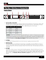
1.  Input Level Meters w/Clip Indicator 

These LED meters show the incoming signal level of each channel and indicate when the input signal is clipping. Input 
level LEDs range from -28 dBu (SIG) to +22 dBu (CLIP). The below table shows the correlation between the input 
meter LEDs and signal level depending on the +4 dBu/-10 dBV switch position on the rear panel. 

Input LEDs (switch set to +4 dBu)

(switch set to -10 dBV)

CLIP

22 dBu

8 dBV

0

19.9 dBu

5.9 dBV

3

17 dBu

3 dBV

10

10 dBu

-4 dBV

20

0 dBu

-14 dBV

SIG

-28 dBu

-42 dBV

NOTE: 

AFS works best when the signal entering the AFS2’s inputs is sufficient. This requires proper gain staging 

between the mixer and AFS2. For maximum performance and proper operation, the average input signal level should 
consistently light the ‘20’ LED, with the ‘10’ LED lighting occasionally. If the signal level is too low, AFS may be slow 
to respond to feedback. See 

‘Gain Structure’ on page 6 

for further information on gain structure.

2.  LCD Display 

This LED backlit LCD display provides the visual cues necessary for navigating and operating the AFS2.

3.  MENU/BACK Button 

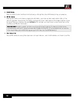
Pressing this button from the Information View Home Screen in Home Mode will enter the AFS2 menus. Pressing it 
from the Filter Plot Home Screen will return to the Information View Home Screen. Pressing it when in any menu will 
move back one level in the current menu hierarchy. Pressing it from the first screen in the menu hierarchy will return to 
Home Mode.

4.  DATA Wheel 

This encoder is used for making on-screen selections and editing parameters. Pressing this DATA wheel from Home 
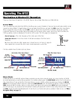
Mode will also toggle between the two available Home Screens. One screen shows detailed information about each set 
filter (i.e., the width, attenuation amount, and set frequency) and the other displays a graphical representation of the set 
AFS notch filters. See 

‘Navigating & Modes Of Operation’ on page 14 

for further information on these Home 

Screens.

Summary of Contents for AFS2

Page 1: ...Owner s Manual ...

Page 2: ...his product In no event shall dbx or its dealers be liable for special or consequential damages or from any delay in the performance of this warranty due to causes beyond their control Technical Support Service If you require technical support contact dbx Technical Support Be prepared to accurately describe the problem Know the serial number of your device this is printed on a sticker attached to ...

Page 3: ... Panel 11 Rear Panel 13 Operating The AFS2 14 Navigating Modes Of Operation 14 Home Mode 14 Menu Mode 14 Wizard Mode 15 Menu Navigation Map 15 The AFS Filters 16 Fixed Filters 16 Live Filters 16 Filter Widths 16 Clearing Filters 17 Linking Unlinking Channels 18 Ringing Out The Sound System 19 Using The Wizard 19 Manual Method 19 Presets 21 Saving Presets 21 Loading Presets 21 Front Panel Lockout 2...

Page 4: ...klit LCD display shows the frequency width and attenuation amount of each set filter Not sure how to ring out a sound system No problem The new Wizard in the AFS2 walks you through the entire setup and ring out procedure Feedback suppression couldn t be any easier Just press the big red Wizard button and follow the on screen instructions The updated AFS algorithm in the AFS2 can now detect and eli...

Page 5: ... Lift feature automatically removes filter assignments that are no longer necessary which in turn maximizes sonic integrity AFS uses precision frequency detection and state of the art processing to determine the exact range of feedback frequencies to remove instead of indiscriminately removing large sections of audio In the past graphic equalizers were used to eliminate feedback from a system This...

Page 6: ... lines cause phase cancellation short a conductor to ground or cause damage to other equipment connected to the AFS2 therefore it is not recommended Connecting to both outputs of a channel simultaneously is perfectly acceptable as long as the combined parallel load is 1 2kΩ or greater This is typically not a problem since most modern day audio devices have been designed with high impedance line in...

Page 7: ...ack processors then your power amplifiers or powered speakers Note that the AFS2 will mute its outputs as it powers up and initializes Once initialized the outputs will automatically unmute WARNING When powering up a fully connected PA system it is advisable to ALWAYS turn on the mixer and rack equipment including the AFS2 first then turn on your amplifiers or powered speakers It s also a good ide...

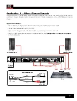
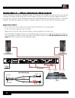
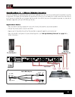
Page 8: ...the average input signal level to the AFS2 should consistently light the 20 LED with the 10 LED occasionally lighting Connection methods 1 2 and 3 above are the preferred way to connect the AFS2 since the insert points on most mixers are pre fader This allows proper signal level to be fed to the AFS2 without the channel subgroup or master fader affecting the level Be sure to check the mixer s manu...

Page 9: ...ft Main Powered Speaker Right Main Powered Speaker Mixer WIZARD 20 10 CLIP 3 0 SIG CH 1 CH 2 INPUT FILTERS 1 2 3 4 5 6 7 8 9 10 11 12 13 14 15 16 17 18 19 20 21 22 23 24 CH 1 CH 2 BYPASS SELECT MENU BACK AFS WIZARD Configure Channel 2 Configure as Stereo Configure Channel 1 A HARMAN INTERNATIONAL COMPANY SALT LAKE CITY UTAH MODEL AFS2 FEEDBACK SUPPRESSION WARNING TO REDUCE THE RISK OF FIRE OR ELEC...

Page 10: ...ps If processing a stereo subgroup the AFS2 should be configured for stereo linked operation See Linking Unlinking Channels on page 18 for further information on this configuration option Left Main Powered Speaker Right Main Powered Speaker Mixer WIZARD 20 10 CLIP 3 0 SIG CH 1 CH 2 INPUT FILTERS 1 2 3 4 5 6 7 8 9 10 11 12 13 14 15 16 17 18 19 20 21 22 23 24 CH 1 CH 2 BYPASS SELECT MENU BACK AFS WI...

Page 11: ...ked operation see Linking Unlinking Channels on page 18 for further information Left Main Powered Speaker Right Main Powered Speaker Mixer WIZARD 20 10 CLIP 3 0 SIG CH 1 CH 2 INPUT FILTERS 1 2 3 4 5 6 7 8 9 10 11 12 13 14 15 16 17 18 19 20 21 22 23 24 CH 1 CH 2 BYPASS SELECT MENU BACK AFS WIZARD Configure Channel 2 Configure as Stereo Configure Channel 1 A HARMAN INTERNATIONAL COMPANY SALT LAKE CI...

Page 12: ... s inputs or the next device in the chain if using a system EQ or active crossover Apply power to the system ensuring to turn the amplifiers or powered speakers on last Ensure the AFS2 is configured for stereo linked operation see Linking Unlinking Channels on page 18 for further information WIZARD 20 10 CLIP 3 0 SIG CH 1 CH 2 INPUT FILTERS 1 2 3 4 5 6 7 8 9 10 11 12 13 14 15 16 17 18 19 20 21 22 ...

Page 13: ...signal level should consistently light the 20 LED with the 10 LED lighting occasionally If the signal level is too low AFS may be slow to respond to feedback See Gain Structure on page 6 for further information on gain structure 2 LCD Display This LED backlit LCD display provides the visual cues necessary for navigating and operating the AFS2 3 MENU BACK Button Pressing this button from the Inform...

Page 14: ...essing and holding a channel s BYPASS button will bring up a menu where you can quickly clear just the Live filters or all filters for the channel WARNING If AFS is enabled and filters are set be careful when bypassing the filters as all filters will be immediately removed from the signal path and sudden feedback could occur It is recommended that you lower the mixer outputs feeding the AFS2 befor...

Page 15: ...or input connections female locking XLR type connectors and 1 4 tip ring sleeve phone connectors Either of these input connector types can be used with balanced or unbalanced connections The maximum input level that the processor can accept is 20 dBu ref 0 775 Vrms 5 Operating Level Switches These switches allow you to select between a nominal operating level of either 4 dBu or 10 dBV for each cha...

Page 16: ...FIXED CH 1 1 500Hz 12 0dB 7 F F F F F F F F F F F L L L L L L L L L L L L L L L L L L L L L L F F F F F F F F F F L SP MUS LIVE SPEECH CHAN 2 Selected Channel Filter Filter Center Frequency Filter Mode Content Mode AFS Filters F Fixed L Live White Box Set Filters Filter Attenuation Amount Filter Q Factor Selected Filter FF F F F F F F F F F F L L L L L L L L L L L CH 1 1 500Hz 100 20k 1k 20 12 0dB...

Page 17: ...ap shows the navigational hierarchy of the AFS2 and how to navigate the unit CHANNEL BYPASS FILTER MODE CONTENT MODE FIXED FILTERS CLEAR MODE CLEAR PRESS SELECT LIVE LIFT LIFT AFTER VIRTUAL HIGHPASS SENSITIVITY AFS Options Menu Parameters LOAD PRESET SAVE PRESET FACTORY DEFAULT Preset Menu Parameters Preset Menu STEREO LINKED POWER UP OPTION DISPLAY TIMEOUT The currently installed software version...

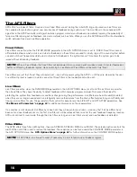
Page 18: ... Fixed filters in the loaded preset will be set Live Filters Live filters are active when the FILTER MODE parameter in the AFS OPTIONS menu is set to LIVE Live filters are smarter than Fixed filters They have the ability to detect feedback within complex program material This makes them ideal for protecting the system from feedback as conditions change during the performance Live filters also have...

Page 19: ...g the DATA wheel 3 Turn the DATA wheel to select the CLEAR MODE parameter then press the DATA wheel 4 Turn the DATA wheel to select which filters you wish to clear Select the LIVE ONLY option to clear only the Live filters Select the ALL option to clear all Live and Fixed filters 5 Press the DATA wheel to jump back to the left column then turn the DATA wheel to select the CLEAR PRESS SELECT option...

Page 20: ...gs but feedback will be detected and notched out independently per channel When clearing filters with the channels linked both channels will be cleared To link unlink channels manually 1 From the Home Screen press the BACK MENU button 2 Turn the DATA wheel to select the SYSTEM MENU option then press the DATA wheel to advance 3 With the STEREO LINK option selected press the DATA wheel 4 Turn the DA...

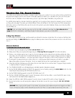
Page 21: ...rmation 3 Perform a sound check and set up a rough mix for all microphones which will be active during the performance When done take note of the mixer s main output fader position mixer master sends if ringing out stage monitors or subgroup faders if ringing out subgroups your target gain when ringing out the system will be around 5 dB above this setting 4 If noise gates are being used on any of ...

Page 22: ...ilters as doing so will remove Fixed filters you just set In other words if the FIXED FILTERS parameter is set to 18 and you have 2 unused Fixed filters you would want to lower the FIXED FILTERS parameter by 2 and no more 14 Set the FILTER MODE parameter to LIVE 15 Go to the CONTENT MODE parameter and select the desired width for the Live filters select the MUSIC SPEECH option for the best all aro...

Page 23: ...o select the PRESET MENU option then press the DATA wheel to advance 3 Turn the DATA wheel to select the SAVE PRESET option then press the DATA wheel to advance 4 Turn the DATA wheel to select the preset memory location at which the preset will be saved NOTE Any settings currently saved to the selected preset will be overwritten 5 Press the DATA wheel to save the settings to the selected preset lo...

Page 24: ... the DATA wheel 4 Turn the DATA wheel to select the amount of time it will take for the front panel to lock after no user activity 5 Press the MENU BACK button repeatedly to return to the Home Screen To enter the PIN and unlock the front panel 1 Turn the DATA wheel and select the number 1 2 Press the DATA wheel to enter 1 as the first number of the PIN 3 Turn the DATA wheel and select the number 2...

Page 25: ...rn the DATA wheel to select the PRESET MENU option then press the DATA wheel to advance 3 Turn the DATA wheel to select the FACTORY DEFAULT option then press the DATA wheel to begin the procedure Factory Hard Reset This reset option involves a boot sequence and can be used to reset all settings including presets back to their factory default state The Factory Hard Reset will reset the following pa...

Page 26: ...is option is optimized for live music sound reinforcement and offers the highest level of sonic quality When this option is selected the AFS algorithm will zero in on the offending feedback frequency while leaving the surrounding frequencies unscathed MUSIC SPEECH Constant bandwidth of 9 Hz below 260 Hz constant Q of 29 at or above 260 Hz This option is optimized for live music sound reinforcement...

Page 27: ...LEAR MODE ALL LIVE ONLY This parameter lets you select whether you would like to clear all filters Live and Fixed or only the Live filters CLEAR PRESS SELECT Selecting this option then pressing the DATA wheel will clear set filters Which filters will be cleared is determined by the option selected for the CLEAR MODE parameter See Clearing Filters on page 17 for more information on clearing filters...

Page 28: ...ITY adjusts the feedback level perceived by AFS For example setting SENSITIVITY to 6 will allow AFS to detect the feedback and notch it out more quickly Conversely setting SENSITIVITY to 6 will cause AFS to be a little more hesitant to set a filter on the feedback until it reaches a higher level When AFS is set to Live Mode SENSITIVITY will work the same way as during Fixed Mode on pure feedback t...

Page 29: ...ng Unlinking Channels on page 18 for further information on linking unlinking channels POWER UP OPTION Current Preset1 Preset2 Preset3 Preset4 Preset5 This parameter determines the settings that will be loaded after power up If the CURRENT option is selected the AFS2 will boot with the same settings it had when it was last powered down If one of the PRESET options is selected the AFS2 will always ...

Page 30: ...INPUT TIP HOT SLEEVE GROUND HOT TIP HOT SLEEVE GROUND SLEEVE RCA PHONO TO TS PHONE FROM SOURCE DEVICE OUTPUT TO NEXT DEVICE INPUT TIP HOT SLEEVE GROUND HOT SLEEVE TIP HOT SLEEVE GROUND TRS PHONE TO TS PHONE FROM SOURCE DEVICE OUTPUT TO NEXT DEVICE INPUT TIP HOT RING COLD SLEEVE GROUND HOT TIP HOT SLEEVE GROUND COLD SLEEVE TS PHONE TO RCA PHONO FROM SOURCE DEVICE OUTPUT TO NEXT DEVICE INPUT TIP HOT...

Page 31: ...29 Dimensions WIZARD 20 10 CLIP 3 0 SIG CH 1 CH 2 INPUT FILTERS 1 2 3 4 5 6 7 8 9 10 11 12 13 14 15 16 17 18 19 20 21 22 23 24 CH 1 CH 2 BYPASS SELECT MENU BACK 19 1 75 17 25 5 875 ...

Page 32: ...kHz BW Type IV dynamic range 119dB A weighted 22kHz BW 117dB unweighted 22kHz BW A D Conversion 24 bit D A PERFORMANCE Dynamic Range 112dB A weighted 109dB unweighted D A Conversion 24 bit SYSTEM PERFORMANCE Sample Rate 48kHz Dynamic Range 107dB A weighted 104dB unweighted 22kHz BW THD N 0 004 typical at 1Vrms input 1KHz at 4 dBu 0 006 typical at 0 2Vrms input 1KHz at 10 dBV Frequency Response 20H...

Page 33: ......
Page 34: ...Phone 801 566 8800 Website dbxpro com Support dbxpro com en US support dbx Professional Products is a registered trademark of Harman AFS2 Owner s Manual PN 5047637 B 2014 Harman All rights reserved ...

Reviews: