,,,,,
yyyyy
,,,,,
yyyyy
18
EDITING LIMITERS
Parameters of the Limiter
The parameters included on the DDP for limiting operations are as follows:
Limter:
(Off/On) Again, the limiter must be turned on to be able to change the parameters and affect the signal.
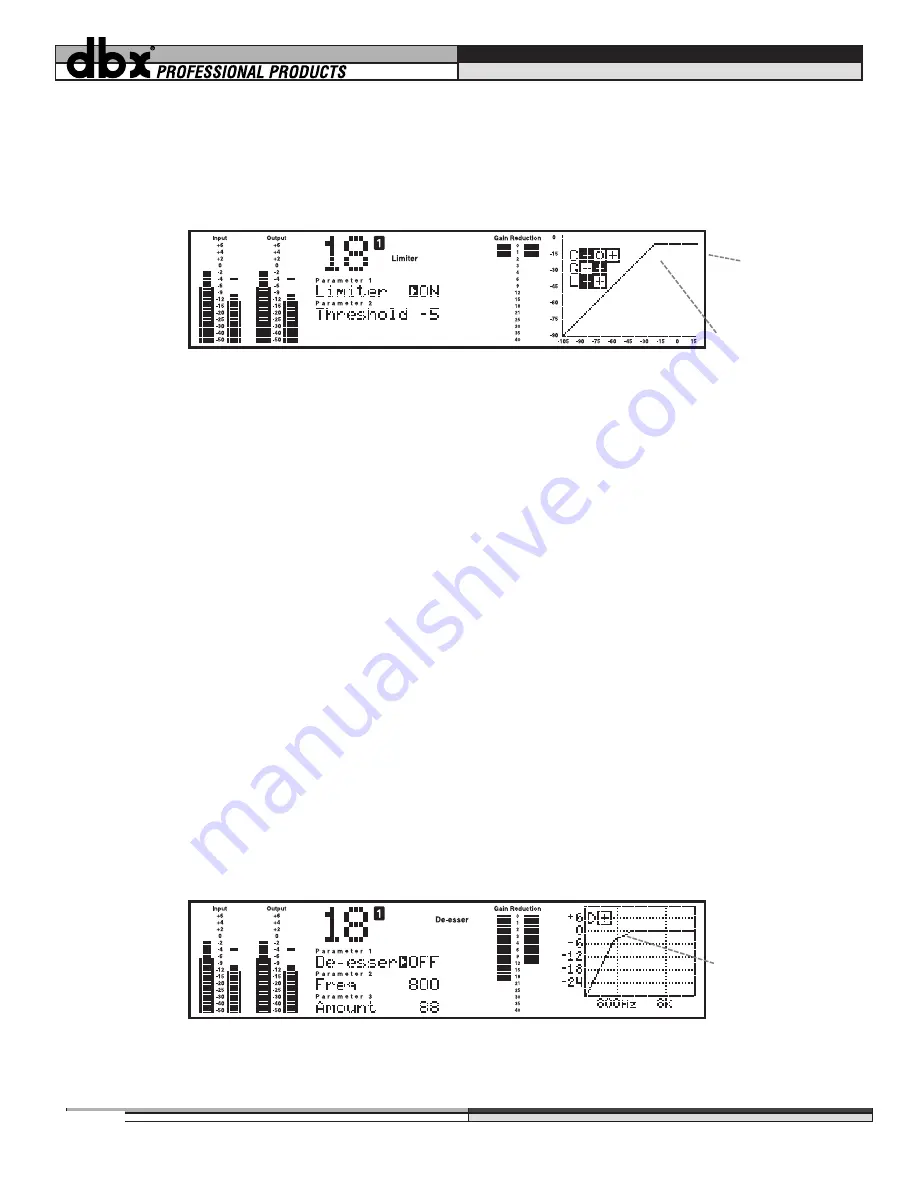
The curve window shows the threshold point of the limiter.
Threshold:
(From -60dB to +4dB) As you move the threshold of the limiter up and down, you see the output
level of the DDP move in relation to the setting. This means that
the limiter of the DDP sets the maximum
output level for the unit
. Remember that very fast transient signals can occasionally “sneak” past the threshold
control of a limiter. If you wish to catch every single transient, set the TCM to a longer delay time, allowing the
DDP to begin to react to a transient signal faster. (For complete information on the TCM™ Transient Capture
Mode controls, refer to the gate section on pages 14 and 15, as well as Appendix #1) Also note that the digital
meters are peak hold meters and they will indicate the same level. whether one sample or hundreds of samples
reach that level. This can be disconcerting, given the fact that it
appears
that much more signal actually gets
through the threshold. Also, it is possible to set the threshold of the limiter below the threshold of the compres-
sor, causing all of the gain reduction to happen in the limiter, and none to happen in the compressor. As you do
this, you will notice that the curve window displays exactly what the threshold level is set to, even to the point of
“overriding” the compression settings. Move the threshold level of the limiter up and down to see how this effects
the composite compression curve. Limiting takes place after the compressor’s gain control setting.
Attack:
(From 0.1ms to 200ms) The attack control sets the speed at which the signal is limited as it crosses over
the threshold into the limiting region.
Release:
(From 360dB/sec to 5dB/sec) The release control sets the speed of release of the signal as it goes below
the threshold, out of the limiting region, and is returned to its normal, unprocessed waveform.
EDITING DE-ESSERS
Parameters of the De-Esser
The parameters included on the DDP for De-Essing operations are as follows:
De-Esser:
(Off/On) Enables or deables the de-esser. When you are not using the de-esser, it should be turned off.
Section 4: Editing/Saving/Recalling Programs
Figure 18: De-Esser parameters and curve
Frequency above
which the de-esser
is sensitive
Figure 17: Limiter parameters and curve
Limiter threshold
Limiter output
level
Summary of Contents for DDP
Page 1: ...y Operator Manual...
Page 16: ...yyyyy yyyyy 13 Section 3 Setup Basic Operation Figure 13b Available Mono Chains...
Page 42: ...FRAN AIS yyyyy yyyyy 39...
Page 82: ...yyyyy yyyyy 79 DEUTSCH...
Page 122: ...yyyyy yyyyy 119 ESPA OL...

