background image

10

220i

DriveRack

®

 User Manual

For your convenience, all editing functions of the DriveRack 220i are performed via the included 
Driveware GUI. This section has been created to act as a tutorial for performing various editing aspects 
of the unit.

 2.1 - DriveRack 220i Philosophy 

The philosophy of the DriveRack 220i is built around the idea of a program. 

Programs

A program consists of processing modules configured to form the desired signal path. The processing 
modules and all their parameters are saved as part of the program. The quickest way to get up and 
running with the DriveRack 220i is to select one of the programs that are already configured. If 
modifications are needed then the program can be reconfigured to select the appropriate processing 
modules and parameters can be edited to taste. All module parameters are part of the program and 
as such they are saved off when the program is stored. These parameters are also saved as part of the 
program file when the program is exported to a computer.

Utilities and Mutes

Utilities and Mutes are global functions and are independent of the program. Utilities and Mutes are not 
saved as part of the program when it is stored but they can be saved as part of the device file. This can 
be helpful as Utilities can be set up just once rather than having to set up the utilities for each program. 
The same applies to Mutes; output Mutes can be used regardless of the program that is being recalled. If 
the need arises to mute an output as part of a program and have that level remain with the program, the 
output level can be set to –inf in the Matrix Mixer. This means that no matter whether the output mute 
is engaged or not, that output will have no output level.

 2.2 - PC Connection 

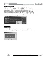
Once the software has been loaded and the DriveRack unit is connected via the included Null Modem 
cable, run the DriveWare Graphic User Interface (GUI) by double clicking on the application icon. You 
will see the DriveWare window open with an icon of the DriveRack 220i unit. Double clicking on the 
unit will open the unit to the program screen where you will be able to see the processing modules and 
the configuration. 

 2.3 - Views 

There are three different views within the DriveWare GUI; Venue view, Unit view, and Module view. 

Venue view

 provides you with an overall system view of the DriveRack network including other 

DriveRack units if you are using 480 series DriveRack units that can be networked together. Double 
clicking on a unit icon in the Venue view takes you to the Unit view. 

Unit view 

(often called program 

screen) provides you with a graphic representation of the configuration of the individual DriveRack unit, 
including all the processing modules and their positions in the signal path. Unit view offers access to 
meters and output muting, program selection and loading, processing configuration, program import and 
export, program storing, as well as utility menu control. Double clicking on the processing module takes 
you to the Module view. 

Module view

 (also called edit screen) provides access to the processing and 

utility parameters. Editing of parameters is done in Module view.

Software Operation

Section 2

Summary of Contents for DriveRack 220i

Page 1: ...User Manual System Processor with Advanced Feedback Suppression 220i...

Page 2: ...qualified service personnel Servicing is required when the ap paratus has been damaged in any way such as power supply cord or plug is damaged liquid has been spilled or objects have fallen into the a...

Page 3: ...Director Engineering Signal Processing 8760 S Sandy Parkway Sandy Utah 84070 USA Date May 31 2012 European Contact Your local dbx Sales and Service Office or Harman Signal Processing 8760 South Sandy...

Page 4: ...atrix EQ 16 3 3 Advanced Feedback Suppression 18 3 4 Automatic Gain Control AGC 20 3 5 De Esser 21 3 6 Ducker 22 3 7 Compressor 22 3 8 Noise Gate 24 3 9 Notch Filters 25 3 10 Matrix Mixer 26 3 11 Post...

Page 5: ...220i Intro Customer Service Info Defining the DriveRack WARRANTY INFO Introduction...

Page 6: ...ontrollers These controllers provide convenient remote control capability of Program change Zone output volume and Muting The zone controllers are easy to install using CAT5 cable and fit in standard...

Page 7: ...ce Be prepared to accurately describe the problem Know the serial number of your unit this is printed on a sticker attached to the top panel If you have not already taken the time to fill out your war...

Page 8: ...show evidence of defect provided the product is returned to dbx WITH RETURN AUTHORIZATION from the factory where all parts and labor will be covered up to a period of two years A Return Authorization...

Page 9: ...220i Section 1 GETTING STARTED Getting Started...

Page 10: ...wired in parallel Zone Control Input RJ 45 connector type This input connection is used to send information and power to the ZC wall controllers Inputs 1 2 The input section of the DriveRack 220i off...

Page 11: ...hen lit indicates that the 220i is connected to the PC When it is flashing the 220i is sending receiving information from the PC CLIP LED This LED when lit indicates that a signal is clipping either i...

Page 12: ...e connections have been made and the unit is powered up you can navigate through the entire signal path of the DriveRack 220i from the included DriveWare GUI The display provides you with a clear and...

Page 13: ...220i Section 2 SOFTWARE OPERATION Software Operation...

Page 14: ...an output as part of a program and have that level remain with the program the output level can be set to inf in the Matrix Mixer This means that no matter whether the output mute is engaged or not t...

Page 15: ...in stereo click on one of the module that you want to link While holding the Ctrl button click the other module that you want to link it to both modules should now be highlighted By right clicking on...

Page 16: ...and Mutes The input and output level meters and mute buttons can be seen by clicking on the METER button in the upper right corner of the program screen Outputs can be muted by clicking on the mute bu...

Page 17: ...process make sure that the Replace an Existing Program button is selected and click OK 2 10 Importing and Exporting To save a program to your computer click on File on the Menu Bar and select Save th...

Page 18: ...d a DriveRack unit can be inserted using the Insert menu from the Menu Bar The unit can be configured and edited just the way a real unit can The program can then be Exported to the computer and saved...

Page 19: ...220i Section 3 DETAILED PARAMETERS Detailed Parameters...

Page 20: ...Routing The signal routing begins at the INPUT ROUTING block of the 220i These parameters are user adjustable on all programs Input 1 Level Inf to 20dB Adjusts the input level from analog input one In...

Page 21: ...to 12 dB This parameter allows you to adjust the level of any one of the 28 bands of the GEQ in 5 dB increments PEQ EQ On Off Turns the PEQ on and off Flat Set Undo This parameter either flattens set...

Page 22: ...equency of your feedback that need to be removed instead of taking out large sections of your sound The AFS module of the 220i allows the user to optimize the elimination of feedback In the past graph...

Page 23: ...ivity settings Values are Speech Q 7 25 Music Medium Q 29 Music High Q 128 NOTE Because lower frequencies have longer wavelengths it is sometimes more difficult to find the exact feedback frequency as...

Page 24: ...to unity This prevents the AGC from adding gain when there is no signal present and raising the system noise floor High level signals are reduced by a fast limiter to prevent distortion by clipping Th...

Page 25: ...removing unwanted vocal sibilance These parameters are user adjustable on all programs and are as follows De Esser On Off Turns the De Esser on or off Freq 800 Hz to 8 00 kHz This is the center freque...

Page 26: ...is attenuated in the second channel when a signal is present in the first channel Hold 0 to 500 m Sec Hold time is the length of time after the signal in the first channel goes below the threshold tha...

Page 27: ...s you choose the exact knee that is needed for the dynamic effect you are looking for Threshold T 40 to 20dBu Threshold is the signal level at which the unit starts to compress the signal If the level...

Page 28: ...ng with lots of fast transients The attack control is not active when in auto mode Hold 0 to 500 m Sec Hold is the time the 220i remains in compression after the signal has dropped below the threshold...

Page 29: ...es 4dB below the threshold Attack 0 1 to 200 m Sec As the signal reaches the threshold area the Attack control sets the speed at which the gate opens Use very fast attack times to catch the fronts of...

Page 30: ...ing the ducker module to one or both outputs Input A Level Inf to 20dB Adjusts the level from signal path A Input B Level Inf to 20dB Adjusts the level from signal path B Output 1 Level Inf to 20dB Ad...

Page 31: ...ell All parametrics are bell shaped 2 HShelf One shelf is High while all others are bell 3 LShelf One shelf is Low while all others are bell and 4 LHShelf One shelf is High and one is Low and the othe...

Page 32: ...uency that the output will achieve Lowpass Out to 20Hz Adjusts the highest frequency that the output will achieve 3 13 Limiter The 220i offers a dedicated Limiter module The Limiters are located on ea...

Page 33: ...s cross the threshold Auto On Off When auto is turned on the 220i will continuously set the attack hold release controls itself Attack 01 to 200 m Sec per band or global This is the speed at which the...

Page 34: ...DriveRack provide the user with the ability to control output levels of the unit and adjust phase compensation of loudspeakers within the signal path The output level control is located in the signal...

Page 35: ...mance low frequency speaker systems Sub Harmonic Synth On Off Turns the Subharmonic Synth module on and off Sub Harmonics Synth 0 to 100 This parameter sets the overall level of the Subharmonic Synthe...

Page 36: ......

Page 37: ...220i Section 4 Program List Zone Control FrontPanelLockout Utilities...

Page 38: ...d list size by using the up and down arrows to the right of the Program List Size indicator Select the programs in the list by clicking on one of the programs then use the up and down arrows at the bo...

Page 39: ...trollers are programmed from the Utility menu in the GUI The ZC 3 and ZC 4 allow program selection from either a wall panel or contact closures The diagrams on the following page show screen shots fro...

Page 40: ...This is the perfect security deterrent for unwanted editing Open the utility menu by selecting Edit on the Menu Bar and then clicking on Utilities Select the tab labeled Misc and select Front Panel Lo...

Page 41: ...220i Section 5 Application Guide APPLICATION GUIDE...

Page 42: ...icrophones to the inputs of the DriveRack 2 Connect the outputs of the DriveRack to the mixer 3 Making sure that all outputs are muted apply power to the mixer and amplifiers 4 Make connections betwee...

Page 43: ...re muted apply power to the mixer and amplifiers Software 1 Select Program 1 Stereo AFS 2 Load the program by pressing the Program Up and Down buttons on the front panel or from the DriveWare GUI 3 Ad...

Page 44: ...and the DriveRack Make connections between the contact closure and the ZC 4 Software 1 Select Program 7 Room Combine 1 2 Load the program from the front panel or from the DriveWare GUI 3 Using the Ut...

Page 45: ...lifiers 4 Make connections between the Zone Controllers and the 220i if applicable Software 1 Select Program 5 Restaurant 2 Load the program from either the front panel of the DriveWare GUI 3 Adjust t...

Page 46: ......

Page 47: ...220i Appendix Appendix...

Page 48: ...l Utility settings will be defaulted and all Security settings will be defaulted Pressing any other button will abort the Factory Reset sequence and the unit will reset normally Factory Soft Reset Pre...

Page 49: ...20dBu A D Performance Type dbx Type IV conversion system Dynamic Range line 113 dB A weighted 110 dB unweighted Type IV dynamic range 119 dB A weighted 22kHz BW 117 dB unweighted 22kHz BW Sample Rate...

Page 50: ...r Similar to programs 4 and 5 but the music is only sent to the output 2 Showroom while paging is sent to both outputs 7 Room Comb 1 This program is the first of two that allows room combining In this...

Page 51: ...cro Processor Front RS 232 Rear RS 232 Programmable Logic CLIP Detect Load Up Down Bypass Channel 1 Threshold Input meter Input Mic Signal Clip Mic Gain 30 60dB D A RF Filter Channel 2 threshold Clip...

Page 52: ...onfigure the unit to not pass audio when the power is off Relay Bypass the normal mode is Relay bypass To change the the gain level or relay jumpers move the jumpers to the desired settings 1 First ma...

Page 53: ...then Copy and Paste parameters where available and otherwise copy the parameters from one unit to the next For our example you would create the correct configuration for the DriveRack 480 and then Cop...

Page 54: ...ust have a unique identification or number chosen using the DIP switches on the rear of the panel see diagram A To wire in parallel each controller must be wired into a port of the ZC BOB with a conne...

Page 55: ...er Manual Diagram A RJ45 CONNECT ONLY TO ZONE CONTROLLER I N P U T IEC6006 5 UL 650 0 80 1342 A RJ45 CONNECT ONLY TO ZONE CONTROLLER I N P U T IEC6006 5 UL 650 0 80 1342 A ID 1 ID 4 Diagram B ID 3 ID...

Page 56: ...8 Position ON 1 2 3 4 5 6 ON 1 2 3 4 5 6 ON 1 2 3 4 5 6 ON 1 2 3 4 5 6 ON 1 2 3 4 5 6 ON 1 2 3 4 5 6 8 8 Brown Ground 1 1 White Orange Voltage Reference 2 2 Orange Controller 1 3 3 White Green Control...

Page 57: ...ndy Parkway Sandy Utah 84070 Phone 801 568 7660 Fax 801 568 7662 Int l Fax 801 568 7583 Questions or comments E mail us at customer dbxpro com or visit our website at www dbxpro com or www driverack c...

Reviews: