background image

Detailed Parameters

®

26

Section 4

DriveRack

™  

PA

DriveRack™ PA User Manual

Section 4

The DriveRack™ PA also offers Compression and Limiter modules.  The Compressor is a full
bandwidth Stereo Compressor located prior to the Crossover.  The Compressor is the perfect
tool for tightening uneven signal sources such as vocals and guitars.  The Limiters are located 
on each stereo output channel and have been strategically placed for speaker and amplifier pro-
tection. Note that Compressor/Limiter threshold metering can be observed on page two of the
Utility section.  The parameters for the Compressor/Limiter are as follows and are user
adjustable.

COMPRESSOR

Compressor On/Off

Turns the Compressor module on and off.

OverEasy  (O) Off to 10

There are ten levels of OverEasy® that can be used for the limiters.  The point when the com-
pressor starts to compress is the "knee." When the compressor starts to reduce the level of a
signal abruptly as it passes over the threshold, this is called "hard knee" compression.
OverEasy® (soft knee as it is sometimes called) is when the volume of the sound is compressed
gradually. OverEasy® compression starts to compress before the level of the signal reaches the 
threshold and reaches full compression after the level has gone above the threshold.
OverEasy® compression, by its very nature, sounds much smoother and more natural and will
be used for most applications. When it is gentle (natural sounding or light) compression that
you are looking for, the compressor offers VariKnee™.  VariKnee™ gives you ten levels of
OverEasy® compression to choose from (1 being almost hard knee and 10 being the most
OverEasy®). This lets you choose the exact knee that is needed for the dynamic effect you are
looking for.

Threshold (T) -40 to +20dBu

Threshold is the signal level at which the unit starts to compress the signal. If the level is set to
-10 dBu, than any signal larger than -10 dBu is compressed while any signal that has a level
that is lower than -10dBu is left at the same signal level. Light compression is where only the
loudest parts of the signal go over the threshold. Very heavy compression can be achieved by
setting the threshold low enough that almost the entire signal content is over the threshold. For
most signals the most natural compression is achieved when most of the signal content remains
just below the threshold and only the peaks cross the threshold.

Ratio (R) 1.0  to Inf:1

Ratio is the amount the unit reduces the signal level of the sound that is above the threshold.
A 2:1 ratio means that if the incoming signal is 2dB over the threshold the unit will compress
the signal, and outputs a signal that only goes 1dB over the threshold. For light compression
choose a lower ratio, while a heavy compression requires a higher ratio. A setting of Inf:1 makes
the compressor act as a limiter.

Gain (G) -20 to +20 dB

This parameter is used to compensate for the gain lost during compression. By using heavy
compression on a signal and then boosting the signal with the output gain, the user can create
a signal that sounds much louder than it actually is.

4.6 Compressor/Limiter  

Summary of Contents for DriveRack

Page 1: ...User Manual Complete Equalization Loudspeaker Control System Featuring Custom Tunings PA...

Page 2: ...ck refer servicing to qualified service personnel or equiv alent This Equipment is intended for rack mount use only SAFETY INSTRUCTIONS NOTICE FOR CUSTOMERS IF YOUR UNIT IS EQUIPPED WITH A POWER CORD...

Page 3: ...ARNING Explosionsfara vid felaktigt batteribyte Anv nd samma batteri typ eller en ekvivalent typ som rekommenderas av apparattil lverkaren Kassera anv nt batteri enligt fabrikantens instruk tion IMPOR...

Page 4: ...n 16 2 10 Navigating the Wizard Section 16 Section 3 Operating the DriveRack PA 3 1 Program Definition 18 3 2 Navigating Factory Programs 18 3 3 Editing Factory Programs 18 Section 4 Detailed Paramete...

Page 5: ...INTRO CUSTOMER SERVICE INFO Defining the DriveRack WARRANTY INFO INTRODUCTION DriveRack PA...

Page 6: ...m needs for years to come The dbx DriveRack PA is the most effective way to manage all aspects of Loudspeaker man agement for Public Address system applications The DriveRack PA essentially becomes th...

Page 7: ...ave correctly followed installation steps and operation procedures If you are still unable to solve a problem contact our Customer Service Department at 801 568 7660 for consultation If you need to re...

Page 8: ...from the factory where all parts and labor will be covered up to a period of two years A Return Authorization number must be obtained from dbx by tele phone The company shall not be liable for any con...

Page 9: ...Getting Started Section 1 DriveRack PA...

Page 10: ...the level from either 4 or 10dBv Ground Lift Switch The ground lift switch lifts the pin 1 chassis ground of both input XLR connectors RTA Input Jack This balanced XLR input is used for the connection...

Page 11: ...miter modules DELAY is used to move to the Delay module PROGRAM is used to enter program mode when pressed UTILITY is used to access the the Utility menu STORE is used to store any program changes WIZ...

Page 12: ...Driverack PA Always make sure that your power amps are the last item turned on and the first turned off Once all of the connections have been made and the unit is powered up you can navigate through t...

Page 13: ...Rack PA Wizard Now that you have made all of your audio connections and have made yourself familiar with the front panel navigation of the unit you can easily optimize your system through the use of t...

Page 14: ...rotating the DATA wheel to select any one of the numerous custom tuned Amplifier options available Note that the top line of the display will either read High Mid or Low depending on your selected sp...

Page 15: ...dit your settings By using your selections the DriveRack will automati cally generate a new program and speaker selection which are used to choose the correct crossover type parameters speaker compens...

Page 16: ...se will toggle between the two modes You can also select either mode to default to in the Utility menu Regardless the display will appear something like this At this point the DriveRack PA will automa...

Page 17: ...er usage will be indicated at the bottom of each page of the feed back elimination effect F indicates an available fixed filter and L indicates an avail able live filter A blocked out F or L indicates...

Page 18: ...n com pleted If you have reached the performance level setting and all of the fixed filters have not been used you may want to return to the page that selects the number of fixed filters and re adjust...

Page 19: ...EDITING FUNCTIONS Editing Functions Section 2 DriveRack PA...

Page 20: ...selected page of the currently selected effect module PREVIOUS PAGE Moves to the previous page in the currently selected effect menu NEXT PAGE Moves to the next page in the currently selected effect m...

Page 21: ...selected program simply use the following procedure From program mode press the EQ button to reach the EQ module to be edited Successive presses of the EQ button will move through each channel Navigat...

Page 22: ...in Inf to 20dB Low High Pass Low Pass High Pass Low Pass High Pass XOVER To edit the parameters of the Crossover used in a selected program simply use the following procedure From program mode press t...

Page 23: ...20dB Ratio 1 1 to Inf 1 Gain 20 to 20dB LIMITER Limiter On Off Over Easy Off 1 10 Threshold 40 20dB COMPRESSOR LIMITER From program mode press the comp limiter button to move to eithter the Compressor...

Page 24: ...12 Mixer gain turn down prompt Select Type Low Med High mode Mixer Gain Adjust WIZARD From program mode press the WIZARD button Pressing the Data Wheel will select the effect parameter to be edited PR...

Page 25: ...OPERATING FUNCTIONS SOFTWARE Section 3 DriveRack PA...

Page 26: ...at utilize carefully constructed routing configurations that have been designed to accommodate virtually any sound reinforcement and installation application The factory programs offer a clear and con...

Page 27: ...store any program changes WIZARD is used to enter the Wizard section which includes SYSTEM SETUP AUTO EQ WIZARD and AFS WIZARD Once you have reached the module that you wish to edit simply use the PRE...

Page 28: ...has been written press the STORE button again and the dis play will now appear something like this Rotate the DATA wheel to select the program to be replaced and press the STORE button and the existin...

Page 29: ...DETAILED PARAMETERS PARAMETERS Section 4 DriveRack PA...

Page 30: ...a guitar pickup or microphone is reproduced by an ampli fication and is repeatedly picked up in phase The AFS uses Precision Frequency Detection and state of the art processing to determine the exact...

Page 31: ...ues are Speech Bandwidth 1 5 octave and Q 7 25 Music Low Bandwidth 1 10 octave and Q 14 5 Music Medium Bandwidth 1 20 octave and Q 29 Music High Bandwidth 1 80 octave and Q 116 Note To guarantee that...

Page 32: ...If this occurs adjust the controls as needed e g increase one or the other of the band levels Experimentation will pay off with smooth full deeply extended bass Remember you are not selecting a freque...

Page 33: ...within the signal path the DriveRack PA also offers a 2 or 3 band parametric EQ after the crossover section The parameters for the post crossover EQ are as follows and are user adjustable PEQ On Off...

Page 34: ...you are looking for the compressor offers VariKnee VariKnee gives you ten levels of OverEasy compression to choose from 1 being almost hard knee and 10 being the most OverEasy This lets you choose the...

Page 35: ...hreshold is the signal level at which the unit starts to compress the signal If the level is set to 10 dBu any signal larger than 10 dBu is compressed while any signal that has a level that is lower t...

Page 36: ...Detailed Parameters 28 Section 4 DriveRack PA DriveRack PA User Manual Section 4 USER NOTES...

Page 37: ...APPLICATION GUIDE Section 5 DriveRack PA...

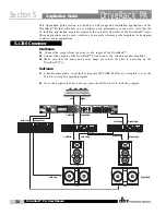
Page 38: ...m the mixer to the inputs of the DriveRack 2 Connect the outputs of the DriveRack PA and run to the selected speaker amplifier 3 Make sure that the mixer and power amps are turned off prior to powerin...

Page 39: ...e DriveRack PA Software 1 From Program mode select factory program F2 3 Way w mSub as a template or use the Wizard to setup the specific program 2 Once the program has been chosen press the DATA wheel...

Page 40: ...ower amps are turned off prior to powering up the DriveRack PA Software 1 From Program mode select factory program F14 MP212 2X4 as a template or use the Wizard to setup the specific program 2 Once th...

Page 41: ...riveRack PA and run to the selected speaker amplifier 3 Make sure that the mixer and power amps are turned off prior to powering up the DriveRack PA Software 1 Use the Wizard to setup the specific pro...

Page 42: ...Application Guide 34 Section 5 DriveRack PA USER NOTES DriveRack PA User Manual...

Page 43: ...Appendix DriveRack PA...

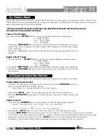
Page 44: ...be defaulted Pressing the PROGRAM button will abort the System Reset sequence and the unit will reset normally The DriveRack PA offer several Quick Key options for initial power up and are as follow...

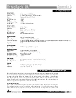
Page 45: ...0 5dB Interchannel Crosstalk 110dB 120dB typical Crosstalk input to output 100dB Power Supply Operating Voltage DO 100 120VAC 50 60 Hz EU 220 240 VAC 56 60 Hz Power Requirements 25 Watts Physical Weig...

Page 46: ...number of consecutive bands of the Graphic EQ you can adjust the level of the asso ciated cross over output gain to match the average boost or cut in the graphic EQ and re pink your room This time the...

Page 47: ...mpressor AFS Notch Filters SubHarmonic Synth 3 Band PEQ 2 Band PEQ 2 Band PEQ Peak Stop Limiter Peak Stop Limiter Peak Stop Limiter Alignment Delay Alignment Delay Alignment Delay Crossover Section 2X...

Page 48: ...2 14 JBL MPro MP415 15 JBL EON1500 16 JBL EON10G2 17 JBL EON15G2 18 JBL SndFactor SF15 19 JBL SndFactor SF25 20 EAW FRz FR129z 21 EAW FRz FR159z 22 EAW FRz FR153z 23 Yamaha S112IV 24 Yamaha S115IV 25...

Page 49: ...rning down the amplifi er input attenuators does not change the potential output of the amplifier it only requires more input voltage to get full output power Many amplifiers will clip with an input l...

Page 50: ...your amplifier you should make sure that the sine wave is within the frequency range of the output band that your are working with Once all the limiters are set up you can now turn the amplifiers back...

Page 51: ...th Sandy Parkway Sandy Utah 84070 Phone 801 568 7660 Fax 801 568 7662 Int l Fax 801 568 7583 E mail us at customer dbxpro com or visit us on the web at www dbxpro com A Harman International Company 18...

Reviews: