background image

Monitor  Application Guide

®

6

DriveRack™

dbx

The following information and illustrations indicate several ways to patch in and optimize a
DriveRack™ system for use in stage monitoring systems.

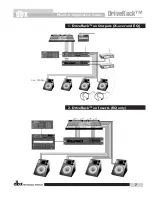
1) DriveRack™ on Outputs (x-over and EQ):

What you need for monitor wedges is: EQs, Notch filters, Crossovers and Compressors  For In-ear
monitors, you need a stereo EQ with stereo Compressors.  Standardize on one unit which will
meets all of your monitor needs.  Simply patch from each mix output on the console into an input
on the DriveRack™ and then from the outputs into the power amps.  Now since the EQ is on the
outputs and not the inserts of each mix when you AFL that mix the EQ setting will not appear in
your sample wedge.  To correct this the sample wedge input must be set to "cue" and then each
channel input on the DriveRack™ is set to "to cue".  What happens now is that every time you
recall a channel on the 480R, the pre x-over setting for that channel is also copied into the "cue"
channel and thus you hear the EQ etc. in your sample wedge and are better able to dial in the
mix for the musician on stage.  Also when using a Soundcraft SM20, Series 5M, Allen & Heath
ML5000 or Midas Heritage mixing desk, the desk will send a midi message to the 480R that will
automatically cue the appropriate DriveRack™ channel when the AFL or PFL button is pushed on
one of the console outputs.

2) DriveRack™ on Inserts (EQ only)

To use the DriveRack™ on inserts as an EQ only unit, simple patch into 4 insert points on the con-
sole and select a full range x-over on each of the input channels.  This gives you four 31-band
graphic EQs or four 9-band parametric EQs per input as well as all the delay, phase, and com-
pressor/limiter functions with using the x-overs.  Sample EQ and AFL as you would with the same
number of analog devices patched.  With the MIDI functionality of the DriveRack™, when an AFL
is pressed on either the Soundcraft SM20, Series 5M, Allen & Heath ML5000 or Midas Heritage mix-
ing desk, it will automatically recall the appropriate channel on the DriveRack™ unit.

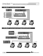
3) DriveRack™ on Outputs (x-over only)

To use the DriveRack™ in an crossover only application, first patch the DriveRack™ on the out-
put section.  From Program mode, manually bypass the all of the EQs that are being utilized in
the DriveRack™.  Once the EQs have been bypassed, make any edits to the crossover sections
from the program edit  mode.

4) DriveRack™ on both inserts and Outputs (EQ and x-over)

To do this two separate DriveRack™ units must be used.  One patched on inserts (as above) the
other on outputs (as above).  All the units can be controlled from a single control surface.   By
utilizing an additional DriveRack unit on the inserts as well as the output section, the performance
exceeds that of a high-priced all-analog system, at a substantially lower price.  

Applications

Summary of Contents for DriveRack

Page 1: ......

Page 2: ...Monitor Application Guide 2 DriveRack dbx Table of Contents Welcome 3 Defining the DriveRack System 3 Applications 6 Making Connections 10 Crossover Block Diagrams 21 Specifications 26...

Page 3: ...Alignment Delays Compressor Limiter on every output Speaker Compensation EQ post crossover Multi level Security System TYPE IV Conversion System Electronically balanced RF filtered XLR Inputs and Out...

Page 4: ...ctronically balanced RF filtered XLR Inputs and Outputs Proprietary RS 485 Control Network RS 232 GUI Interface for computer display and configuration 480R DriveRack features Dedicated remote interfac...

Page 5: ...t panel interfaces In addition the 481 offers euroblock connectors as opposed to the XLR connectors found in the 480 and 482 DriveRack units The 480 481 and 482 include features such as pre crossover...

Page 6: ...the AFL or PFL button is pushed on one of the console outputs 2 DriveRack on Inserts EQ only To use the DriveRack on inserts as an EQ only unit simple patch into 4 insert points on the con sole and se...

Page 7: ...2 DriveRack on Inserts EQ only 1 DriveRack on Outputs X over and EQ Monitor Application Guide DriveRack dbx 7...

Page 8: ...Monitor Application Guide 8 DriveRack dbx 4 DriveRack on both inserts and Outputs EQ and X over 3 DriveRack on outputs X over only...

Page 9: ...Monitor Application Guide DriveRack dbx 9...

Page 10: ...other units in the DriveRack net work link RS485 Control Bus Input RJ 45 connector type This input network connection is used to receive information being sent from other units in the DriveRack networ...

Page 11: ...on Buttons The function buttons of the 480 DriveRack allow access to all editing and navigating functions of the 480 DriveRack Parameter Knobs The parameter knobs of the 480 DriveRack allow the user t...

Page 12: ...tch Turns the 480 DriveRack on and off IEC Power Cord Receptacle The 481 comes with an International power supply that will accept voltages ranging from 100V 240V at frequencies from 50Hz 60Hz An IEC...

Page 13: ...n either inputs 1 or 2 or 3 or 4 RS232 Host Connection This DB 9 type connection is used to send and receive information to and from the GUI interface Program Up and Down These program up and down but...

Page 14: ...240V at frequencies from 50Hz 60Hz An IEC cord is included MIDI In and Out Thru Connectors These connectors provide full MIDI functionality to the 482 DriveRack The In Out and Thru jacks allow you to...

Page 15: ...balanced XLR connectors Inputs 3 and 4 offer Line RTA switches that allow you to run a real time audio analyzer micro phone directly into the input of the 482 DriveRack The four XLR inputs of the 482...

Page 16: ...ith four independent 12 segment lightpipe input meters that range from 30 to 22 dBu Threshold Meters The threshold meters indicate that the threshold level has been exceeded within the dynamics sec ti...

Page 17: ...with the real time audio analyzer Phantom Power Switch This Thru network connection is used to pass information to other units in the DriveRack net work link MIDI In and Out Thru Connectors These conn...

Page 18: ...the user with all of the vital process ing information of the DriveRack including signal routing configuration modes effect block editing and RTA displays Function Buttons The function buttons of the...

Page 19: ...k Output Mutes The eight output mute buttons are used for independent output muting on all eight outputs of the 480R DriveRack System Mute Button The SYSTEM mute button when pressed and lit is used to...

Page 20: ...or type This input connector is used to connect to the 480R RS485 Link to Network Master DB 9 connector type This input connector is used to connect 480R to the network master RS485 Link to 480R RJ 45...

Page 21: ...The following are crossover configurations found in the 480 481 and 482 DriveRack units Crossover Block Diagrams Monitor Application Guide DriveRack dbx 21...

Page 22: ...Monitor Application Guide 22 DriveRack dbx...

Page 23: ...Monitor Application Guide DriveRack dbx 23...

Page 24: ...Monitor Application Guide 24 DriveRack dbx...

Page 25: ...Monitor Application Guide DriveRack dbx 25...

Page 26: ...z BW 119 dB typical with program material A weighted 22kHz BW Sample Rate 48kHz A D Wordlength 24 bits D A Performance Dynamic Range 112 dB unweighted 115 dB A weighted Sample Rate 48kHz D A Wordlengt...

Page 27: ...r 4 can be selected as an RTA mic input Connectors Euroblock Type Electronically balanced RF filtered Impedance 40k Maximum Input Level Hardware selectable for 30 22 14 dBu Max input RTA Level 10 dBu...

Page 28: ...12 18 or 24 dB octave for Butterworth or Bessel filters 12 24 36 or 48 dB octave for Linkwitz Riley filters Post EQ Type Parametric Number 4 EQ bands per output channel Range 15 dB range Dynamics Typ...

Page 29: ...weighted 22kHz BW Sample Rate 48kHz A D Wordlength 24 bits D A Performance Dynamic Range 112 dB unweighted 115 dB A weighted Sample Rate 48kHz D A Wordlength 24 bits System Performance Internal Wordle...

Page 30: ...ink noise inserted on selected input s Phase Compensation Number One per output channel Amount 0 180 degrees phase shift Output Polarity Reversible Miscellaneous Output Transformers Optional Network P...

Page 31: ...A 10 dB to 70 dB w 60 dB typical Miscellaneous Network Proprietary RS 485 link GUI RS 232 interface for computer display and RTA Microphone Optional ROM Upgrade Flash upgradeable through RS 232 Dimens...

Page 32: ...mer dbxpro com or visit our World Wide Web home page at www dbx pro com A Harman International Company MONITOR APPLICATION GUIDE 8760 South Sandy Parkway Sandy Utah 84070 Phone 801 568 7660 Fax 801 56...

Reviews: