TR1616
Owner’s Manual
8
making connectionS–cabling
It is recommended that power on all interconnecting equipment be turned off before making
audio connections to the TR1616.
Power
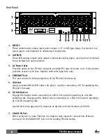
Connect the included IEC power cable to this fused AC inlet. Connect the other end to an
available AC power outlet. The TR1616 does not have a power switch. An AC power strip or power
conditioner can be used for switching power to the TR1616 on and off.
Note:
If the fuse becomes compromised, replace with the same type fuse only. See “Specifications”
for fuse information.
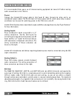
Analog Inputs
These combination inputs accept XLR or 1/4”
analog connections. Use the XLR inputs for
connecting low impedance microphones and DI
boxes and the 1/4” inputs for line level devices
with balanced or unbalanced connections. The
wiring conventions of these connectors are
shown to the right.
1/4”
XLR
Tip
Hot
Pin 1
Ground
Ring
Cold
Pin 2
Hot
Sleeve
Ground
Pin 3
Cold
Note:
All microphones and devices requiring phantom power must be connected using the XLR
input connections.
Analog Outputs
These XLR analog outputs provide balanced
audio connections. The wiring convention of
these connectors are shown to the right.
XLR
Pin 1
Ground
Pin 2
Hot
Pin 3
Cold
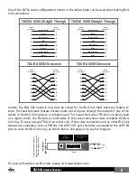
BLU link
The SNAKE IN, SNAKE OUT, LOOP IN, and LOOP OUT ports are all BLU link ports and require the
same type of cabling. BLU link is a proprietary point to point networking protocol that requires
CAT5e or better cable. The BLU link ports are auto sensing, so you can use either a straight
through cable (same termination on both ends) or crossover cable between them. The maximum
allowable cable length of a single BLU link connection is 100 m (328 ft). By closing the BLU link
ring, BLU link’s built-in fault tolerance feature can be utilized.


