background image

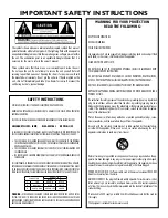
The symbols shown above are internationally accepted symbols that warn of 

potential hazards with electrical products. The lightning flash with arrowpoint in 

an equilateral triangle means that there are dangerous voltages present within 

the unit. The exclamation point in an equilateral triangle indicates that it is 

necessary for the user to refer to the owner’s manual.

These symbols warn that there are no user serviceable parts inside the unit. 

Do not open the unit. Do not attempt to service the unit yourself. Refer all 

servicing to qualified personnel. Opening the chassis for any reason will void 

the manufacturer’s warranty. Do not get the unit wet. If liquid is spilled on the 

unit, shut it off immediately and take it to a dealer for service. Disconnect the 

unit during storms to prevent damage.

WARNING FOR YOUR PROTECTION

READ THE FOLLOWING:


KEEP THESE INSTRUCTIONS

HEED ALL WARNINGS

FOLLOW ALL INSTRUCTIONS

the apparatus shall  not be exposed to dripping or splashing liquid and no object filled 

with liquid, such as vases, shall be placed on the apparatus.

CLEAN ONLY WITH A DRY CLOTH.

DO NOT BLOCK ANY OF THE VENTILATION OPENINGS. INSTALL IN ACCORDANCE WITH 

THE MANUFACTURER’S INSTRUCTIONS.

DO NOT INSTALL NEAR ANY HEAT SOURCES SUCH AS RADIATORS, HEAT REGISTERS, 

STOVES, OR OTHER APPARATUS (INCLUDING AMPLIFIERS) THAT PRODUCE HEAT.

ONLY USE ATTACHMENTS/ACCESSORIES SPECIFIED BY THE MANUFACTURER.

UNPLUG THIS APPARATUS DURING LIGHTNING STORMS OR WHEN UNUSED FOR LONG 

PERIODS OF TIME.

Do not defeat the safety purpose of the polarized or grounding-type plug. A polarized 

plug has two blades with one wider than the other. A grounding type plug has two 

blades and a third grounding prong. The wide blade or third prong are provided for your 

safety. If the provided plug does not fit your outlet, consult an electrician for replace-

ment of the obsolete outlet.

Protect the power cord from being walked on or pinched particularly at plugs, conve-

nience receptacles, and the point where they exit from the apparatus.

Use only with the cart stand, tripod bracket, or table specified by the manufacture, 

or sold with the apparatus. When a cart is used, use caution when moving the cart/

apparatus combination to avoid injury from tip-over.

Refer all servicing to to qualified service personnel. Servicing is required when the ap-

paratus has been damaged in any way, such as power-supply cord or plug is damaged, 

liquid has been spilled or objects have fallen into the apparatus, the apparatus has been 

exposed to rain or moisture, does not operate normally, or has been dropped.

POWER ON/OFF SWITCH: The Power switch used in this piece of equipment DOES NOT 

break the connection from the mains.

MAINS DISCONNECT: The plug shall remain readily operable. For rack-mount or instal-

lation where plug is not accessible, an all-pole mains switch with a contact separation 

of at least 3 mm in each pole shall be incorporated into the electrical installation of the 

rack or building.

If connected to 240V supply, a suitable CSA/UL certified power cord shall be used for 

this supply.

This Equipment is intended for rack mount use only.

SAFETY INSTRUCTIONS

NOTICE FOR CUSTOMERS IF YOUR UNIT IS EqUIPPED WITH A POWER CORD.

WARNING: THIS APPLIANCE SHALL BE CONNECTED TO A MAINS SOCKET OUTLET WITH A PROTECTIVE 

EARTHING CONNECTION.

THE CORES IN THE MAINS LEAD ARE COLOURED IN ACCORDANCE WITH THE FOLLOWING CODE:

GREEN aNd YELLOW - EaRth        BLUE - NEUtRaL        BROWN - LivE

AS COLOURS OF THE CORES IN THE MAINS LEAD OF THIS APPLIANCE MAY NOT CORRESPOND WITH 

THE COLOURED MARKINGS IDENTIFYING THE TERMINALS IN YOUR PLUG, PROCEED AS FOLLOWS:

•    THE CORE WHICH IS COLOURED GREEN AND YELLOW MUST BE CONNECTED TO THE TERMINAL 

IN THE PLUG MARKED WITH THE LETTER E, OR WITH THE EARTH SYMBOL, OR COLOURED GREEN, 

OR GREEN AND YELLOW.

•    THE CORE WHICH IS COLOURED BLUE MUST BE CONNECTED TO THE TERMINAL MARKED N OR 

COLOURED BLACK.

•  THE CORE WHICH IS COLOURED BROWN MUST BE CONNECTED TO THE TERMINAL MARKED L OR 

COLOURED RED.


THIS EqUIPMENT MAY REqUIRE THE USE OF A DIFFERENT LINE CORD, ATTACHMENT PLUG, OR BOTH, 

DEPENDING ON THE AVAILABLE POWER SOURCE AT INSTALLATION. IF THE ATTACHMENT PLUG NEEDS 

TO BE CHANGED, REFER SERVICING TO qUALIFIED SERVICE PERSONNEL WHO SHOULD REFER TO THE 

TABLE BELOW. THE GREEN/YELLOW WIRE SHALL BE CONNECTED DIRECTLY TO THE UNITS CHASSIS.

CONDUCTOR

WIRE COLOR

Normal

Alt

L

LIVE

BROWN

BLACK

N

NEUTRAL

BLUE

WHITE

E

EARTH GND

GREEN/YEL

GREEN

WaRNiNG:

 IF THE GROUND IS DEFEATED, CERTAIN FAULT CONDITIONS IN THE UNIT OR IN THE 

SYSTEM TO WHICH IT IS CONNECTED CAN RESULT IN FULL LINE VOLTAGE BETWEEN CHASSIS AND 

EARTH GROUND. SEVERE INjURY OR DEATH CAN THEN RESULT IF THE CHASSIS AND EARTH GROUND 

ARE TOUCHED SIMULTANEOUSLY.

IMPORTANT SAFETY INSTRUCTIONS

Summary of Contents for TR1616

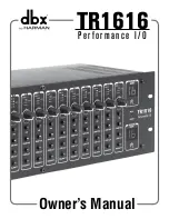
Page 1: ...TR1616 Performance I O Owner s Manual...

Page 2: ...qualified service personnel Servicing is required when the ap paratus has been damaged in any way such as power supply cord or plug is damaged liquid has been spilled or objects have fallen into the a...

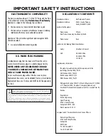
Page 3: ...irective Roger Johnsen Director Engineering Signal Processing 8760 S Sandy Parkway Sandy Utah 84070 USA Date November 14 2012 European Contact Your local dbx Sales and Service Office or Harman Signal...

Page 4: ...or visit www dbxpro com If you need to return a product to the factory for service YOU MUST FIRST CONTACT TECHNICAL SUPPORT TO OBTAIN A RETURN AUTHORIZATION NUMBER NO RETURNED PRODUCTS WILL BE ACCEPTE...

Page 5: ...defect provided the product is returned to dbx WITH RETURN AUTHORIZATION from the factory where all parts and labor will be covered up to a period of two years A Return Authorization number must first...

Page 6: ......

Page 7: ...k 8 Analog Inputs 8 Analog Outputs 8 Applications 10 Personal Monitoring w dbx PMC16s 10 16 x 16 Digital Snake w Personal Monitoring 12 32 x 32 Digital Snake w Personal Monitoring 14 32 Channel BSS So...

Page 8: ...ining and programming Whether you require additional analog inputs or outputs in an existing BLU link compatible BSS Audio Soundweb London system a digital snake solution for live sound or a complete...

Page 9: ...0 C when equipment is in use Although the unit is shielded against radio frequency and electromagnetic interference extremely high fields of RF and EMI should be avoided where possible Quick Start To...

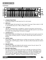
Page 10: ...nput from being overdriven The button s LED will light when the function is engaged 5 LOW CUT Button These buttons enable and disable the low cut filter for each channel This filter is a low cut filte...

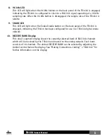
Page 11: ...en the Snake Enable button on the back panel of the TR1616 is engaged indicating the TR1616 has been configured for use in a TR1616 digital snake network 10 RECEIVE BANK Display This dual 7 segment di...

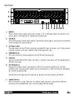
Page 12: ...place with same type fuse only 4 ETHERNET Port This port allows for future expansion of the TR1616 s feature set 5 USB Port Using a standard Mini USB cable this port is used for connecting a PC for up...

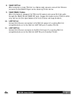
Page 13: ...through the SNAKE IN and SNAKE OUT ports Engage this button on two TR1616s which carry and receive the signal between the front of house and stage locations 10 LOOP IN Port Connect this Ethercon conn...

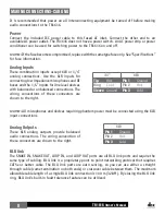
Page 14: ...ns The wiring conventions of these connectors are shown to the right 1 4 XLR Tip Hot Pin 1 Ground Ring Cold Pin 2 Hot Sleeve Ground Pin 3 Cold Note All microphones and devices requiring phantom power...

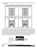
Page 15: ...ork ring must be closed for the BLU link fault tolerance feature to work The fault tolerance feature ensures audio will still pass through the network if one of the cables in the BLU link network is c...

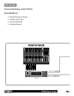
Page 16: ...g w dbx PMC16s Recommended for Small Performance Venues Portable Live Sound Houses Of Worship Rehearsal Spaces BLU link LOOP OUT Receive Bank 1 Transmit Bank 1 1 Mixer Outputs Transmit Bank 1 Receive...

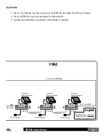
Page 17: ...ected to the network System can be further expanded in the future if needed IN BLU link Legend BLU link Connection Analog Connection Power Supply Power Supply Power Supply Powered Wedge Monitor Powere...

Page 18: ...nk ring without using this extra cable connection To do this leave the snake mode disabled on the 1 TR1616 and make the following connections 2 TR1616 SNAKE OUT 1 TR1616 LOOP IN 1 TR1616 LOOP OUT 2 TR...

Page 19: ...plifiers or loudspeaker management processor for the main PA speakers System can be further expanded in the future if needed BLU link LOOP OUT to IN SNAKE IN SNAKE OUT Instrument Instrument Powered We...

Page 20: ...nsembles Orchestras BLU link to SNAKE IN 100 m 328 ft max Mixer Outputs From Instruments On Stage From Instruments On Stage BLU link LOOP OUT to LOOP IN BLU link LOOP OUT to LOOP IN BLU link from SNAK...

Page 21: ...eeding the amplifiers or loudspeaker management processor for the main PA speakers System can be further expanded in the future if needed Power Supply Power Supply BLU link LOOP OUT to LOOP IN Instrum...

Page 22: ...ink Connection Analog Connection 32 CHANNEL ANALOG ON RAMP FOR BLU LINK COMPATIBLE BSS SOUNDWEB LONDON SYSTEM BLU link BLU 800 BLU 800 BLU link LOOP OUT to LOOP IN BLU link OUT to LOOP IN BLU link LOO...

Page 23: ...ts to the BLU link network on ramp the other is using two TR1616s for adding 32 channels of analog outputs to the BLU link network off ramp However the systems shown in these two diagrams can also be...

Page 24: ...nnel Bank Channels Available In Bank Supported Sample Rates 1 1 16 48 kHz 96 kHz 2 17 32 48 kHz 96 kHz 3 33 48 48 kHz 96 kHz 4 49 64 48 kHz 96 kHz 5 65 80 48 kHz 96 kHz 6 81 96 48 kHz 96 kHz 7 97 112...

Page 25: ...port or at the SNAKE IN port Flashing Display Segments When this display flashes an invalid BLU link connection is detected at the LOOP IN or SNAKE IN port NOTE The RECEIVE BANK display indicates cab...

Page 26: ...hones Note All devices connected to the TR1616 which require phantom power must be connected using the XLR connections 4 Engage the POLARITY buttons on any channels which require it such as the bottom...

Page 27: ...The Firmware Updater application for the TR1616 requires a Windows PC To perform a firmware update 1 Download the Firmware Updater application from www dbxpro com 2 Follow the on screen instructions...

Page 28: ...TR1616 Owner s Manual 22 Block Diagram...

Page 29: ...TR1616 Owner s Manual 23 Dimensions 5 250 19 000 6 950 17 370 0 125 5 745...

Page 30: ...8kHz THD N Typically 0 002 at 1kHz 0dBu XLR input gain set to minimum Interchannel Crosstalk 100dB 22Hz to 22kHz ADC Latency 37 Fs 0 77msec at 48kHz Phantom Power 48VDC applied to XLR pins 2 and 3 thr...

Page 31: ...m Cable Length 100m 328ft on Category 5e cable between devices Maximum number of nodes 60 Maximum number of channels 256 at 48kHz 128 at 96kHz Latency 11 Fs 0 23msec at 48kHz Pass Through Latency 4 Fs...

Page 32: ...8760 South Sandy Parkway Sandy Utah 84070 PH 801 566 8800 FAX 801 566 7005 http www dbxpro com dbx is a registered trademark of Harman Copyright Harman TR1616 Owner s Manual 5035742 A Printed in China...

Reviews: