Etherpoll User’s Guide
6
Physical Details
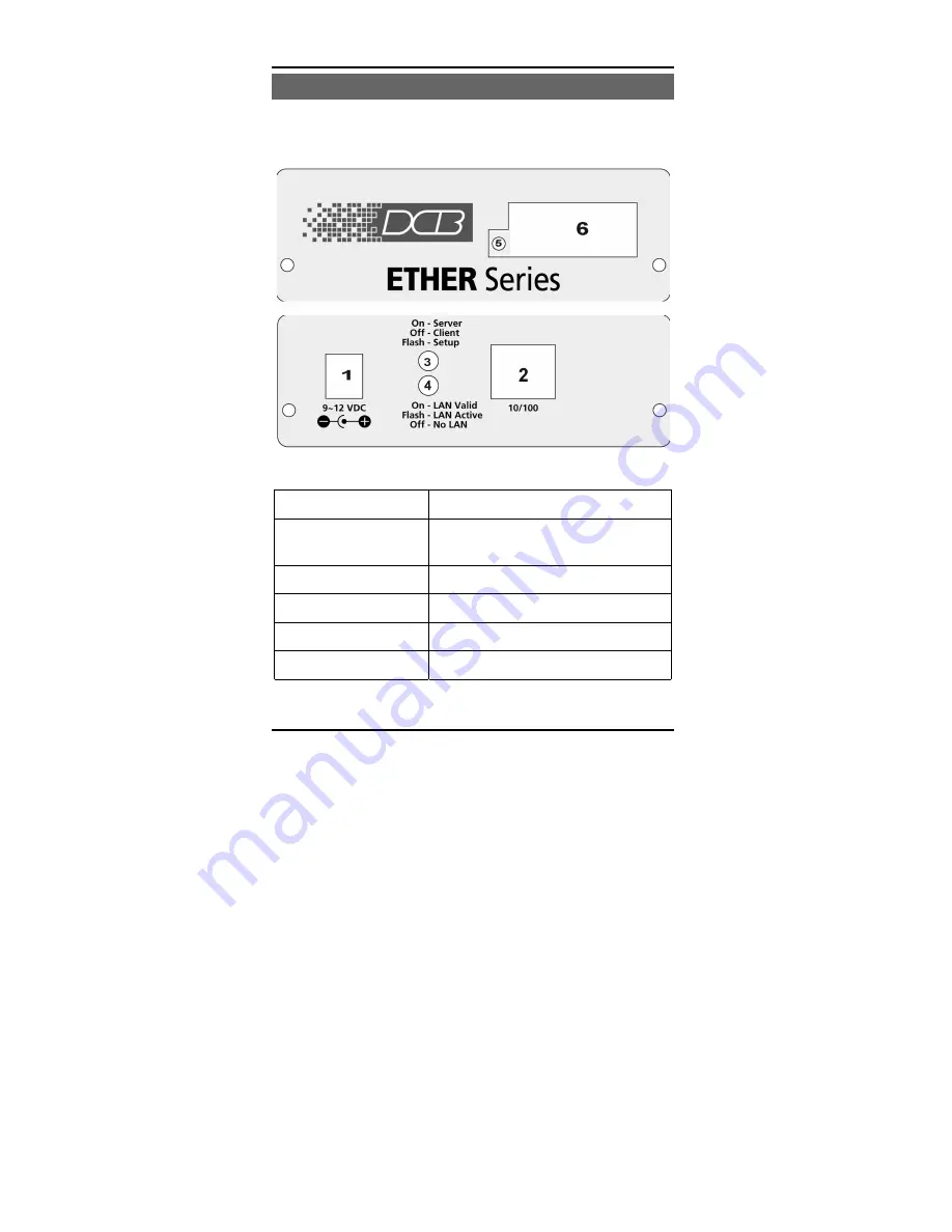
The EtherPoll front and rear panels are shown below.
Figure 1: EtherPoll
1
Power port
Connect the power adapter here.
2
10/100Base-T
port
Connect LAN cabling here.
3
Red LED
Client/Server/Setup Indicator
4
Red LED
LAN Activity Indicator.
5
Green LED
Connection Indicator.
6
RS-232 Port
DE-9 (DB-9) RS-232 Interface.
Summary of Contents for EtherPoll
Page 1: ...Revised October 7 2002 Firmware Version 4 1 EtherPoll User s Guide...
Page 2: ......
Page 4: ......
Page 8: ......
Page 56: ...48...


