background image

11

INSTALLATION

GAS HOOK-UP

LP TANK  REQUIREMENTS

A dented or rusty LP gas cylinder may be hazardous and

should be checked by your LP supplier.  Never use a cylinder
with a damaged valve.

The LP gas cylinder must be constructed and marked in 

accordance with the specifications for LP gas cylinders of the
U.S. Department of Transportation (DOT ) and designed for
use with a Type 1 system only.  

Do not change the regulator/hose assembly from that 

supplied with the unit or attempt to use a Type 1 equipped
regulator/hose assembly with a standard 510 POL tank/valve
assembly.  The cylinder must be provided with a shut-off
valve terminating in an LP gas supply cylinder valve outlet 
specified, as applicable, for connection Type 1.  

If the appliance is stored indoors, the cylinder must be

disconnected and removed from the appliance.  

Cylinders must be stored outdoors in a well ventilated area

out of the reach of children. 

Gas cylinder supply must be turned off when not in use.

NATURAL GAS HOOK-UP (continued)

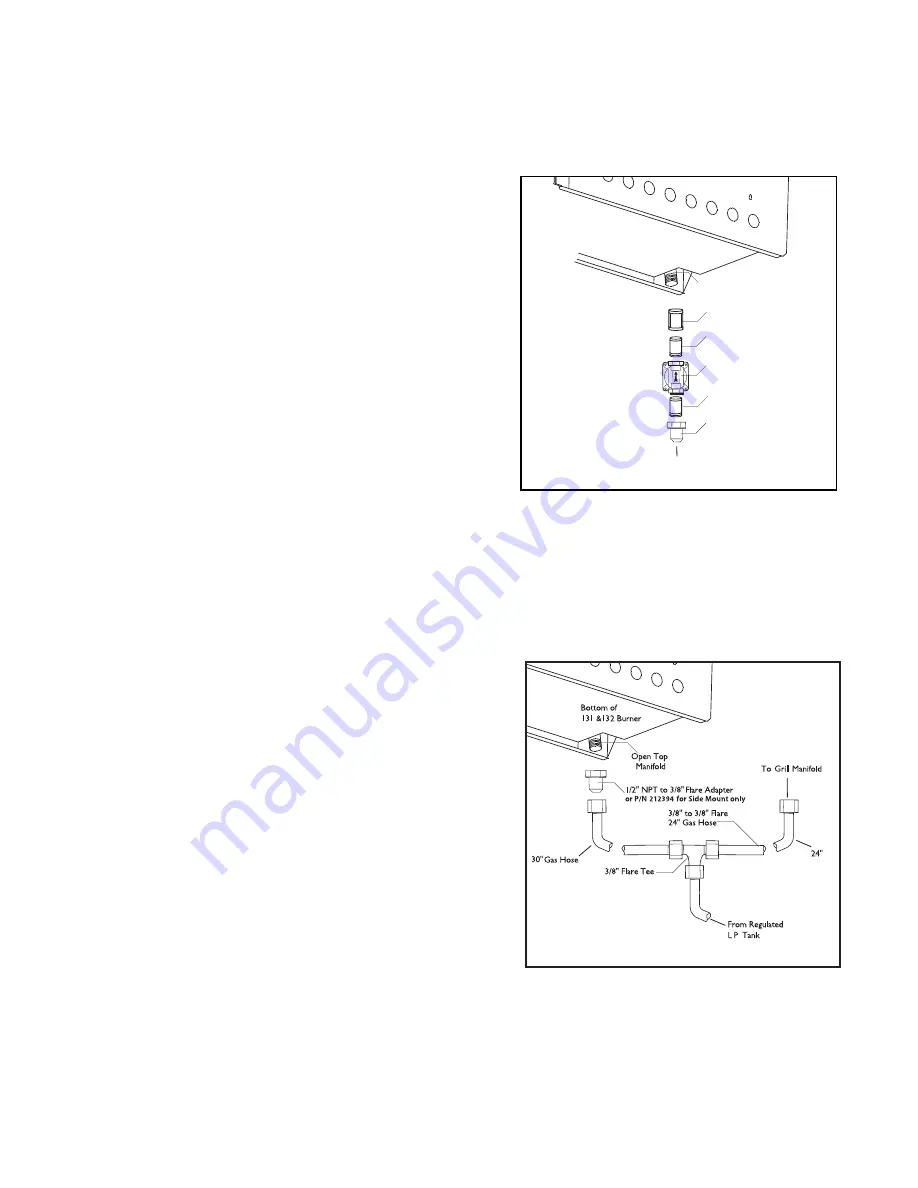
To hook-up the fittings supplied with the side burner, assemble as shown in Fig.04.  Use joint compound on
male threads only.

Do not use joint compound on the flare end of the 1/2” NPT
to 3/8” flare adapter.  Ensure that the regulator arrow points
in the direction of gas flow-towards the unit, away from the
supply.  

Do not forget to place the installer-supplied gas valve in an
accessible location.

LP GAS HOOK-UP

CONNECTION: 1/2” NPT male with 3/8” flare adapter 
(included).  Use 90º elbow 1/2” NPT with 3/8” flare 
(P/N 212394) for side mount models only when installing on
the cart.  Use sealer on 1/2” NPT threads only. 

OPERATING PRESSURE:  10.0” W.C. side burner uses the LP
regulator from adjoining grill.

SUPPLY PRESSURE: 11” to 14” W.C. 

Apply joint compound to the threaded end of the side burner gas
inlet and tighten the adapter to the pipe. Assemble the 24” and 30” hoses to the 3/8” flare tee, as shown in
Fig.05.  Tighten the regulator hose to the remaining fitting of the 3/8” flare tee.

Open Top

Manifold

Bottom of
131 &132 Burner

1/2" Coupling

1/2" NPT x 2.0”
Nipple

1/2" NPT to 3/8"

Flare Adapter

Regulator

To Gas Supply

1/2" NPT x 2.0”
Nipple

FIG. 04 Natural Gas

FIG. 05 LP Gas

Summary of Contents for BGB131

Page 1: ...THE PROFESSIONAL SIDE BURNER Installation Use and Care Guide MODELS BGB131 BGB132 BGB131 BI BGB132 BI ...

Page 2: ......

Page 3: ... a fire or explosion may result causing property damage personal injury or death Do not store or use gasoline or other flammable vapors and liquids in the vicinity of this or any other appliance An LP cylinder not connected for use shall not be stored in the vicinity of this or any other appliance WARNING Do not try lighting this appliance without reading the Lighting Instructions section of this ...

Page 4: ...lt in Model 8 9 Gas Hook up 10 11 Leak Testing 12 Burner Adjustment 12 Installer Checklist 13 USING THE SIDE BURNER Lighting Instructions 14 CARE AND MAINTENANCE 15 TROUBLESHOOTING 16 PARTS LIST Single Side Burner BGB131 BGB131 BI 17 Double Side Burner BGB132 BGB132 BI 18 WIRING DIAGRAM Single and Double Side Burner 19 SERVICE 20 WARRANTY 21 22 ...

Page 5: ...p the area surrounding the side burner clear and free from combustible materials gasoline other flammable liquids or vapors charcoal lighter fluid and trash Do not obstruct the flow of combustion and ventilation air to the side burner On cart mounted units keep area beneath the burner free of debris If the burner is built in do not store gas cylinders beneath the unit without adequate ventilation ...

Page 6: ...t to disconnect any gas connections while your burner is in use or the gas supply is on When the side burner is stored indoors the gas supply must be disconnected and if using an LP gas cylinder the cylinder must be stored outdoors in a well ventilated area Keep any electrical supply cord away from the heated surfaces of the professional side burner On cart mounted units never move without first a...

Page 7: ...stallation and may contain extra hardware for your convenience Contents Qty Part No 2 211375 5 211323 4 211278 4 211371 4 211394 1 211442 2 211242 Washer Flat 1 4x 938 Screw 1 4 20X1 2 Screw 10 Washer 10 Nut 10 Screw 10 24x1 2 Pan Head Shoulder Bolt 1 4 20x5 16 Tools Required Eye Goggles Work Gloves 10 mm Wrench or Socket 3 32 Allen Wrench Power Screwdriver or Variable Speed Drill with Phillips ti...

Page 8: ... cover grate and drip pan from the side burner STEP 2 Bolt the support brackets to the grill cart side panel with 4 1 4 x 20 bolts provided Note For the BGB131 side burner only use 2 10 sheet metal screws 211242 to bolt the back support bracket SUPPORT BRACKET BOLT FIG 01 ...

Page 9: ...ghten Adjust the side burner until it is level to the grill then tighten securely 2 Bolt the support brackets to the bottom of the side burner with 4 10 24 machine screws nuts and washers provided 3 Replace the drip pan grate and cover Note Once the side burner is assembled refer to the Gas Requirements section for proper gas hook up requirements SIDE BURNER BOLT 1 4 20 Shoulder Bolt 1 4 20 x 5 16...

Page 10: ... as exposure to wind proximity to traffic paths and keeping any gas supply lines as short as possible Locate the side burner only in a well ventilated area Never locate the side burner in a garage breezeway shed or other such enclosed areas It is recommended that ventilation holes are provided in the enclosure in the event of a gas leak The counter and supporting ledges or deck must be level and f...

Page 11: ...12 BGB132 BI 22 3 4 note the deck is not required SIDE BURNER DIMENSIONS REAR FRONT IGNITION BURNER IGNITION 10 5 8 10 5 8 12 12 14 9 16 14 9 16 11 3 8 2 16 1 16 10 1 8 22 1 8 2 10 1 8 26 5 8 Single Side Burner Double Side Burner 3 1 8 3 1 8 1 2 1 2 FRONT FRONT REAR REAR SIDE SIDE STANDARD CONSTRUCTION CUTOUT REQUIREMENTS ...

Page 12: ...LE 1 The appliance and its individual shut off valve must be disconnected from the gas supply piping system during any pressure testing of that system at test pressures in excess of 1 2 PSIG 3 5kPa The appliance must be isolated from the gas supply piping system by closing its individual manual shut off valve during any pressure testing of the gas supply piping system at test pressures equal to or...

Page 13: ...AL GAS HOOK UP continued To hook up the fittings supplied with the side burner assemble as shown in Fig 04 Use joint compound on male threads only Do not use joint compound on the flare end of the 1 2 NPT to 3 8 flare adapter Ensure that the regulator arrow points in the direction of gas flow towards the unit away from the supply Do not forget to place the installer supplied gas valve in an access...

Page 14: ...th burners typical of those used in restaurants Fig 07 These burners are designed for maximum cleanability and controlability The burner should never be operated if the cap is not in place BURNER EFFICIENCY AND FLAME CHARACTERISTICS It is necessary to keep the burner ports and the igniters clean for proper lighting and efficient performance of the burners The burner flame should burn completely ar...

Page 15: ...ent burner lit Knob s turn freely Bezel s centered Flame adjusted Pressure regulator connected and set for 4 0 W C Natural 11 2 W C LP gas Manual shut off valve installed and accessible Unit tested and free of leaks User informed of gas supply shut off valve location Battery installed in module properly and generates ignition spark when activated PLEASE LEAVE THESE INSTRUCTIONS WITH THE USER USER ...

Page 16: ... try again If the burner will not light after several attempts check the troubleshooting instructions on page 16 MATCH LIGHTING Hold a lit fireplace match near the burner ports turn the control knob counterclockwise to HI Rotate the knob immediately once the burner is lit to the desired setting Note If you are using propane gas a slight pop or flash may occur at the burner ports a few seconds afte...

Page 17: ...Y A stainless steel aeration pan and drip tray with a stainless steel handle is located under the burner It collects any boil overs or spills Pull forward to remove Spills should be washed off as soon as possible to prevent baked on soil BURNERS For proper lighting and performance keep the burners clean It is necessary to clean the burners if they do not light even though the igniter clicks if the...

Page 18: ... metal is too far gap should be 1 8 or dirty If there is a spark is there gas supplied to the unit and is the line purged of air See Fig 04 and Fig 05 Does the other burner of a dual burner model operate Check the orifice or venturi for blockage Check the burner for obstructions or dirt See page 15 Check for proper gas supply or wrong gas type Is the side burner in a dusty area Move to less dusty ...

Page 19: ...PAN HANDLE DBI BGA131 BI MODEL 214366 DRIP PAN HANDLE 131 132 BGB131 MODEL 214428 14 1 5VDC BATTERY AA 221154 ITEM DESCRIPTION PART NO 15 BEZEL 210935 16 CONTROL KNOB 211188 17 IGNITION MODULE 211872 18 WIRE BLACKW TERMINALS 8 211823 19 WIRE BLACKW TERMINALS 10 211826 20 TUBING 5 16 9 LENGTH 212399 21 ELBOW 1 8NPT X 5 16T O D 212396 22 FERRULE 5 16 212313 23 NUT M22 JET HOLDER 210468 24 NUT 1 2 24...

Page 20: ... BGA132 BI MODEL 214366 DRIP PAN HANDLE 131 132 BGB132 MODEL 214428 14 1 5VDC BATTERY AA 221154 15 BEZEL 210935 ITEM DESCRIPTION PART NO 16 CONTROL KNOB 211188 17 IGNITION MODULE 211872 18 WIRE BLACKW TERMINALS 10 211826 19 WIRE BLACKW TERMINALS 18 221058 20 TUBING 5 16 21 LENGTH 221956 21 ELBOW 1 8NPT X 5 16T O D 212396 22 TUBING 5 16 9 LENGTH 212399 23 NUT M22 JET HOLDER 210468 24 FERRULE 5 16 2...

Page 21: ... N 210562 SINGLE SIDE BURNER DOUBLE SIDE BURNER 1 5 VOLT ALKALINE BATTERY P N 221154 GND TERMINAL TERMINAL NOTE HIGH VOLTAGE AT TERMINALS Switch is built into module Switch is built into module SPARK ELECTRODE P N 210562 BATTERY IGNITION MODULE P N 211872 BATTERY IGNITION MODULE P N 211872 ...

Page 22: ...ode located on the inside of the left side of the appliance Gas Type Date of installation A brief description of the problem Your satisfaction is of the utmost importance to us If a problem cannot be resolved to your satisfaction please write or email us at Write Fisher Paykel Appliances Inc Attention DCS Customer Care 5900 Skylab Road Huntington Beach CA 92647 Email customer care fisherpaykel com...

Page 23: ...is Limited Warranty shall be provided by Fisher Paykel Appliances Inc or its Authorized Service Agent during normal business hours HOW LONG DOES THIS LIMITED WARRANTY LAST Our liability under this Limited Warranty for the entire product expires ONE YEAR from the date of purchase of the Product by the first consumer Our liability under this Limited Warranty for the structural integrity of the exter...

Page 24: ... of your local DCS Authorized Service Agent or believe the Product is defective and wish service under this Limited Warranty please contact your dealer or call us at TOLL FREE 1 888 936 7872 or contact us through our web site www dcsappliances com You may be required to provide reasonable proof of the date of purchase of the Product before the Product will be serviced under this Limited Warranty C...

Page 25: ...23 NOTES ...

Page 26: ...24 NOTES ...

Page 27: ...LE BRÛLEUR LATÉRAL PROFESSIONNEL Manuel d utilisation et d entretien et installation MODÈLES BGB131 BGB132 BGB131 BI BGB132 BI ...

Page 28: ...on d utilisation et d entretien avant d utiliser installer ou effectuer l entretien de cet appareil Cet appareil de cuisson à gaz pour l extérieur n est pas conçu pour être installé sur des véhicules récréatifs des bateaux ou des pièces sans aération Pour usage en plein air uniquement AVERTISSEMENT 1 Évitez de stocker ou d utiliser de l essence ou tous autres liquides et vapeurs inflammables à pro...

Page 29: ...chement du gaz 10 11 Test de détection des fuites 12 Réglage des brûleur 12 Liste de contrôle 13 UTILISATION DU DRÛLEUR LATÉRAL Instructions d allumage 14 NETTOYAGE GÉNÉRAL 15 DÉPANNAGE 16 LISTE DES PIÈCES Brûleur latéral simple modèles BGB131 ET BGB131 BI 17 Brûleur latéral double modèles BGB132 ET BGB132 BI 18 SCHÉMA DE CÂBLAGE Brûleur latéral simple et double 19 SERVICE 20 GARANTIE 21 22 ...

Page 30: ... autres lieux clos Gardez la zone entourant l appareil dégagée et exempte de matériaux combustibles d essence et autres vapeurs ou liquides inflammables de liquide d allumage pour charbon de bois ou de déchets Évitez d obstruer le flot d air de combustion et de ventilation dirigé vers l appareil Si l appareil est monté sur un chariot gardez la zone en dessous du brûleur exempte de débris Si le brû...

Page 31: ...du brûleur ou lorsque l alimentation en gaz est ouverte Lorsque l appareil est rangé à l intérieur l alimentation en gaz doit être déconnectée et si vous utilisez une bouteille de gaz propane rangez celle ci à l extérieur Gardez tout cordon électrique à l écart des parties chaudes de l appareil Si l appareil est monté sur un chariot ne le déplacez jamais avant que le brûleur latéral ou le gril ait...

Page 32: ...ral et un kit de matériel universel destiné à l installation qui comprend du matériel supplémentaire pour votre commodité Outils requis Contenu Qté Réf 2 211375 5 211323 4 211278 4 211371 4 211394 1 211442 2 211242 Rondelle plate 1 4x 938 Lunettes de sécurité Gants de travail Clé ou douille 10 mm Clé Allen 3 32 po Tournevis mécanique ou perceuse à vitesse variable avec embout Phillips no 2 Vis 1 4...

Page 33: ... les supports au panneau latéral du chariot de gril à l aide de quatre 4 boulons 1 4 x 20 fournis Remarque Pour le brûleur latéral BGB131 uniquement utilisez deux 2 vis à tôle no 10 211242 pour fixer le support arrière Support Boulon INSTALLATION BRÛLEUR LATÉRAL BGB131 132 À CHARIOT 30 PO FIG 01 ...

Page 34: ...nsuite 2 Fixez les supports à la partie inférieure du brûleur latéral à l aide de quatre 4 vis à métaux no 10 24 d écrous et de rondelles fournis 3 Replacez le ramasse gouttes la grille et le couvercle Remarque Une fois le brûleur latéral assemblé reportez vous à la section Exigences concernant le gaz pour les exigences à respecter pour le branchement du gaz BRÛLEUR LATÉRAL BOULON 1 4 20 BOULON À ...

Page 35: ...e circulation nécessité de garder les conduites d alimentation en gaz le plus court possible Placez l appareil dans un lieu bien aéré Ne placez jamais l appareil à l intérieur d un garage abri passage couvert ou autre lieu clos Il est recommandé de prévoir des trous de ventilation dans l enceinte au cas où une fuite de gaz se produirait Le comptoir et les pièces d appui ou la base de support doive...

Page 36: ...quise 2 DIMENSIONS REAR FRONT IGNITION BURNER IGNITION 30 48 cm 12 po 36 98 cm 14 9 16 po 28 89 cm 11 3 8 po 40 8 cm 16 1 16 po 56 20 cm 22 1 8po 67 63 cm 26 5 8 po 7 94 cm 3 1 8 po 1 27 cm 1 2 po 5 08 cm 2 po 5 08 cm 2 po 26 99cm 10 5 8 po 26 99cm 10 5 8 po 25 72cm 10 1 8 po 25 72cm 10 1 8 po 1 27 cm 1 2 po 7 94 cm 3 1 8 po 30 48 cm 12 po 36 98 cm 14 9 16 po vue de face vue de face vue arrière vu...

Page 37: ... totale de gaz de l appareil les brûleurs étant tous sur HIGH Tableau 1 ci dessous TABLEAU 1 L appareil et son robinet d arrêt doivent être déconnectés du système d alimentation en gaz durant les tests de pression lorsque celle ci est supérieure à 3 5 kPa 1 2 PSIG Isolez l appareil du système d alimentation en gaz en fermant son robinet d arrêt durant les tests de pression si celle ci est inférieu...

Page 38: ...gulateur pointe en direction du débit de gaz vers l appareil dans le sens opposé à l alimentation de gaz N oubliez pas de placer le robinet d arrêt fourni par l installateur dans un endroit facilement accessible BRANCHEMENT DU GAZ PROPANE CONNEXION Raccord mâle 1 2 po NPT avec adaptateur évasé 3 8 po inclus Utilisez un raccord mâle 1 2 po NPT avec adaptateur évasé 3 8 po avec coude de 90º réf 1852...

Page 39: ... de brûleurs similaires à ceux que l on utilise dans les restaurants Fig 07 Ces brûleurs sont conçus pour être extrêmement faciles à nettoyer et régler Ne faites jamais fonctionner le brûleur sans son capuchon EFFICACITÉ DES BRÛLEURS ET CARACTÉRISTIQUES DE LA FLAMME Il est nécessaire de maintenir les ports des brûleurs et les allumeurs dans un état de propreté afin d assurer l allumage correct et ...

Page 40: ...ement Cadran s centré s Flamme ajustée Régulateur de pression connecté et réglé pour 4 0 po C E gaz naturel ou 11 2 C E gaz propane Robinet d arrêt manuel installé et accessible Appareil testé et exempt de fuites Utilisateur informé de l emplacement du robinet d arrêt de l alimentation de gaz Pile installée correctement dans le module produit une étincelle d allumage lorsqu activée VEUILLEZ LAISSE...

Page 41: ...lé de se dissiper Si le brûleur ne s allume pas après plusieurs tentatives consultez la section de dépannage à la page 16 ALLUMAGE À L ALLUMETTE Tenez une allumette près des ports du brûleur et tournez le bouton de réglage dans le sens antihoraire pour le mettre sur HI Retirez la main dès que le brûleur s allume Mettez le bouton de réglage sur le niveau désiré Remarque Il se peut qu un léger crépi...

Page 42: ...récipient à graisse à poignée en acier inoxydable se trouvent sous le brûleur Ils servent à recueillir les débordements ou déversements Tirez pour l enlever Nettoyez immédiatement tout déversement pour éviter que les salissures ne cuisent sur place BRÛLEURS Pour assurer un bon allumage et une bonne performance des brûleurs gardez les dans un état propre Vous devez nettoyer les brûleurs s ils ne s ...

Page 43: ... être de 3 2 mm 1 8 po ou sale S il y a une étincelle vérifiez l alimentation en gaz et purgez l air qui pourrait se trouver dans la conduite Voir les Figures 03 et 04 L autre brûleur dans le cas d un brûleur double fonctionne t il Vérifiez si l orifice ou le venturi est bouché Vérifiez si le brûleur est obstrué ou sale Voir page 15 Vérifiez que l alimentation et le type de gaz sont corrects L app...

Page 44: ... MOD BGB141 224825 13 RAMASSE GOUTTES POIGNÉE MOD BGA131 BI 214366 RAMASSE GOUTTES POIGNÉE131 132 MOD BGB131 214428 14 PILE AA 1 5V C C 221154 NO DESCRIPTION RÉF 15 CADRAN 210935 16 BOUTON DE RÉGLAGE 211188 17 MODULE D ALLUMAGE 211872 18 FIL NOIR AVEC BORNES 8 PO 211823 19 FIL NOIR AVEC BORNES 10 PO 211826 20 TUBE 5 16 PO 9 PO DE LONG 212399 21 COUDE NPT 1 8 X 5 16 DIAM EXT TOT 212396 22 FERRULE 5...

Page 45: ... RAMASSE GOUTTES POIGNÉE MOD BGA132 BI 214366 RAMASSE GOUTTES POIGNÉE131 132 MOD BGB132 214428 14 PILE AA 1 5V C C 221154 15 CADRAN 210935 NO DESCRIPTION RÉF 16 BOUTON DE RÉGLAGE 211188 17 MODULE D ALLUMAGE 211872 18 FIL NOIR AVEC BORNES 10 PO 211826 19 FIL NOIR AVEC BORNES 18 PO 221058 20 TUBE 5 16 PO 21 PO DE LONG 221956 21 COUDE NPT 1 8 X 5 16 DIAM EXT TOT 212396 22 TUBE 5 16 PO 9 PO DE LONG 21...

Page 46: ...BRÛLEUR LATÉRAL SIMPLE BRÛLEUR LATÉRAL DOUBLE PILE ALCALINE 1 5 V Réf 221154 Terre BORNE BORNE REMARQUE HAUTE TENSION AUX BORNES L interrupteur est intégré au module L interrupteur est intégré au module ÉLECTRODE Réf 210562 MODULE D ALLUMAGE DE PILE Réf 211872 MODULE D ALLUMAGE DE PILE Réf 211872 ...

Page 47: ...sur le côté gauche de l appareil Type de gaz Date d installation Brève description du problème Votre satisfaction revêt la plus grande importance pour nous Si un problème n est pas résolu à votre entière satisfaction veuillez communiquer avec nous par courrier ou courriel Écrivez nous à l adresse suivante Fisher Paykel Appliances Inc Attention DCS Customer Care 5900 Skylab Road Huntington Beach CA...

Page 48: ...le Tout service couvert par cette garantie limitée sera assuré par Fisher Paykel Appliances Inc ou son agent de service DCS agréé durant les heures d ouverture normales QUELLE EST LA DURÉE DE CETTE GARANTIE LIMITÉE Notre responsabilité en vertu de cette garantie limitée concernant l intégralité du produit expire UN AN à partir de la date d achat du produit par le premier acheteur Notre responsabil...

Page 49: ...ous avez des questions concernant l utilisation du produit que vous cherchez le nom de l agent de service DCS agréé local ou que pensez que le produit est défectueux et désirez le faire réparer dans le cadre de cette garantie limitée veuillez contacter votre distributeur ou nous appeler au numéro suivant NUMÉRO SANS FRAIS 1 888 936 7872 ou contactez nous par l intermédiaire de notre site Web www d...

Page 50: ...23 REMARQUE ...

Page 51: ......

Page 52: ...pecifications or design without notice Fisher Paykel Appliances Inc 5900 Skylab Road Huntington Beach CA 92647 Customer Care 888 936 7872 Fax 714 372 7003 www dcsappliances com Nous améliorons constamment ses produits et se réserve le droit de modifier les spécifications ou la conception de ses produits sans aucun préavis ...

Reviews: