background image

1

2

3

4

7

5

6

8

9

11

10

S M A L L   OV E N

26

Summary of Contents for C 364 GD

Page 1: ...ystems Inc PROFESSIONAL 48 36 30 ALL GAS RANGE 48 AND 36 GAS COOKTOP MODELS Retain this manualforfuturerefe rence P PA AR RT T L LI IS ST T S SE ER RV VI IC CE E M MA AN NU UA AL L RG CANADIAN GAS ASSOCIATION APPROVED R ...

Page 2: ...CS wereservetherightto changespecificationsordesignwithout notice Litho in USA P N 10582 REV 2 6 98 5800 Skylab Road Huntington Beach CA 92647 714 372 7000 Fax 714 372 7001 Direct Parts Customer Service 888 281 5698 Dynamic Cooking Systems Inc ...

Page 3: ...ervicingthera n ge itisfirstimportant toaccura telydefinetheexactdetailsofthecomplaint andthenassessthecauseofthedefect Complete InstallationInstructionsareincludedwitheachappli anceandshouldbeconsultedtocheckforproperinstal l ationpractices Chargesre l atedtoInstallationarenot cove redunderwa rranty Commonforaproductthis l a rgeandheavyisdamageduetore cklesshandlingby t ru ckingfirm s orInstallat...

Page 4: ...beprovidedbyAuthorizedFactoryAgent duringnormalworkinghours Installationorstart up Normaladjustmenttoburners gasregulators etc Cleaningofignitersand orgeneralmaintenance Shippingdamage Servicebyanunauthorizedagency Damageorrepairsdueto servicebyanunauthorizedagencyortheuseofunauthorized parts Overtime weekends holidaylaborrates Discolorationofthegriddleplate Improperinstallation suchas noregulator...

Page 5: ...rifice turnthat bu rneron thepressureshouldread5 0 W C forNaturalGas and10 0 W C forL P Gas Tu rnonotherbu rners andcheckforanex cessivedropinpressure Alarge d ropinpressureindicatesagassupplyproblemrelat edtoinstallation notcove redbyservicewa rranty CHECK ELECTRICAL SUPPLY First checktoseeiftheelectricityhasbeenturnedon Next checkpowertothecordinthebackof therangeandatthewallreceptacle Ifpoweris...

Page 6: ...GE MODEL IDENTIFICATION 36 GAS RANGE MODEL IDENTIFICATION MODEL DCS RG 484GG MODEL DCS RG 486GL MODEL DCS RG 486GD MODEL DCS RG 304 MODEL DCS RG 366 MODEL DCS RG 364GL MODEL DCS RG 364GD RG MODEL IDENTIFICAT I O N ...

Page 7: ...P MODEL IDENTIFICAT I O N 5 48 GASCOOKTOP MODEL IDENTIFICATION 36 GAS COOKTOPMODELIDENTIFICATION MODEL DCS C 484 GG MODEL DCS C 486 GL MODEL DCS C 486 GD MODEL DCS C 364 GD MODEL DCS C 366 MODEL DCS C 364 GL ...

Page 8: ... 7 9 8 10 11 12 13 14 15 16 17 18 19 20 21 22 23 24 25 25 26 31 30 29 27 28 32 33 582fig02 eps BODY PARTS ASSEMBLY 6 27 Oven Door Assembly 90184 02 12 Oven Door Assembly 90184 01 RG 304 Oven Door Assembly 90184 03 ...

Page 9: ...SIDE DOOR PANEL RG 48 36 90094 02 RG 304 OVEN OUTSIDE DOOR PANEL 11A 90184 02 27 90184 01 12 OVEN DOOR ASSEMBLY 90184 03 RG 304 DOOR ASSEMBLY 1 2 17001 DCS LOGO SM COOKTOPS 17001 03 DCS LOGO LG RANGES 1 3 90187 02 27 OVEN DOOR HANDLE RG 48 36 90187 03 RG 304 OVEN DOOR HANDLE 1 4 18164 DOOR HANDLE ENDCAP 1 5 90112 12 DOOR OUTSIDE PANEL 1 6 90187 01 12 DOOR HANDLE 1 7 90107 27 DOOR INSULATION RETAIN...

Page 10: ...sulation 15 17 BACK GUARDS ASSEMBLY 8 R A N G E H I G H S H E L F B A C K G U A R D C O O K T O P L O W B A C K B A C K G U A R D C O O K T O P I S L A N D T R I M B A C K G U A R D C O O K T O P H I G H S H E L F B A C K G U A R D R A N G E L O W B A C K B A C K G U A R D R A N G E I S L A N D T R I M B A C K G U A R D ...

Page 11: ...ETAINER 90039 01 RG 36 LOW BACK INSULATION RETAINER 90039 02 RG 304 LOW BACK INSULATION RETAINER 9 90038 RG 48 LOW BACK FRONT SHEET 90038 01 RG 36 LOW BACK FRONT SHEET 90038 02 RG304 LOW BACK FRONT SHEET 10 90245 01 RG48 TOP ASSEMBLY 90245 02 RG36 TOP ASSEMBLY 90245 03 RG304 TOP ASSEMBLY 11 90248 01 RG 48 BACK SHEET 90248 02 RG 36 BACK SHEET 90248 03 RG 304 BACK SHEET 12 90249 01 RG 48 INSULATION ...

Page 12: ...EMBLY IT IS CRITICAL FOR PROPER PERFORMANCE THAT THE SWITCHES SUPPLYING POWER TO THE SPARK MODULE ARE PLUGGED INTO THE SAME NUMBER TERMINAL AS THE ELECTRODE SERVING THE BURNER IS PLUGGED INTO e g OPEN TOP SPARK IGNITER OUTPUT 1 MUST BE ON THE SAME BURNER SERVED BY THE OPEN TOP SWITCH PLUGGED INTO POWER INPUT 1 1 0 E L E C T R I C A L S C H E M A T I C ...

Page 13: ...ULE 15 12116 SIMMER VENTURI FRONT 16 12114 MAIN VENTURI FRONT 17 16006 TERMINAL BLOCK 18 15109 VALVE SCREW PLUG WASHER 19 16075 POWER CORD RANGES 16005 POWER CORD COOKTOPS 20 13071 SPARK SWITCH SIMMER STD BURNER 21 14006 PL BEZEL 22 14125 SIMMER BURNER KNOB 23 14124 SIMMER BLOCK O RING 24 13070 SIMMER BLOCK 13005 80 SIMMER ORIFICE HOOD LP GAS 13005 80 SIMMER ORIFICE HOOD NATURAL GAS 25 13005 50 OR...

Page 14: ...e Ovenatthefrontoftheunit behindtheKickPanel withovenon B TheThermalValveandconnections supplyingtheGrill withGrillturnedon C O RingbetweentheSimmerBlockand SimmerValveforallOpenTopBurners with bu rnerson Isthe ignitersparking Thesparkshouldbe jumpingtothebrassbu rnerring A Make surethattheleadtotheelectrodeis secure aswellastheleadtotheSparkModuleand thatthereispoweralso B SparkSwitchesatcontrolk...

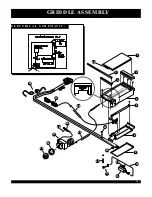
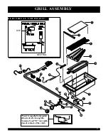
Page 15: ...22 1 2 5 6 8 9 10 13 14 15 7 17 16 18 19 20 3 4 11 12 21 23 24 26 25 GRIDDLE ASSEMBLY 1 3 E L E C T R I C A L S C H E M A T I C L N ...

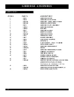
Page 16: ...BOW ASSEMBLY 13 18166 MANIFOLD ADAPTER 14 18165 PIPEPLUG 15 15109 VALVE SCREW PLUG WASHER 16 16046 1 INDICATOR LIGHT 17 13010 3 GRIDDLE THERMOSTAT 18 14006 PL BEZEL 19 14129 GRIDDLE THERMOSTAT KNOB 20 16077 FIBERGLASS SLEEVE 21 16006 TERMINAL BLOCK 22 16075 POWER CORD RANGES 16005 POWER CORD COOKTOPS 23 16077 FIBERGLASS SLEEVE 24 13005 48 ORIFICE HOOD NATURAL GAS 48 DMS ORIFICE PIN LP GAS 55 DMS I...

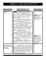
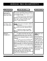
Page 17: ...fo r continuity between the two 2 terminals on the face of the valve If none remove replace 7 If the Thermal Valve is OK Remove thewiresfrom the Griddle Igniter and check the igniter leads for continuity If none remove replace igniter 8 If the Igniter is OK Check the NeutralReturn Wi re for continuity to the neu tral white wire of the powersupplycord 1 Verify Gas supply to the unit Tu rn the Gas s...

Page 18: ...rcycles thegriddleplateshouldhavere a ched equilibrium 2 You llneedaknobwithaholedrilledthro u g h thecentertoallowaflat tippedscre wdrivertobeinserted throughit Withtheknobinplace insertathinblade fl at tippedscrewdriverthroughtheknobandnestit intothesmallslottedscrewinthethermostat itmay benecessarytoclearthescrewofasmallamountof sealant 3 Notethetempera tureshownonthegrid dlethermometer then wh...

Page 19: ... 4 5 6 7 8 17 16 13 9 19 20 21 10 12 14 15 11 22 GRILL ASSEMBLY 1 7 E L E C T R I C A L S C H E M A T I C LIVE NEUTRAL Powerissuppliedtotheigniter thermalvalvethroughthe common and NC normally closed contactsoftheswitch ...

Page 20: ...UG 11 13005 48 ORIFICE HOOD NAT GAS 48 DMS ORIFICE PIN L P GAS 55 DMS INTEGRAL TO THERMAL VA LVE 12 16001 MICROSWITCH 13 13068 SIMMER VALVE STANDARD 14 18030 ELBOW 15 15109 BOLT GASKET 16 90260 CAM GRILL SWITCH 17 14006 PL BEZEL 18 14130 GRILL KNOB 19 16077 FIBERGLASS SLEEVE 20 16006 TERMINAL BLOCK 21 16075 POWER CORD RANGES 16005 POWER CORD COOKTOPS 22 150112 SPEED CLIP CAM GRILL SWITCH 23 14026 ...

Page 21: ...hus de energizing to NC contact Test the switchmanually if non operational remove replace 6 If switch is OK Remove the wires from the Thermal Valve and check for continu ity between the two 2 terminals on the faceof the valve If none remove replace 7 If the Thermal Valve is OK Remove thewiresfrom the Grill Igniter and check the igniter leads for continuity If none remove replace igniter 8 If the I...

Page 22: ... 2 If gasispresent through the Manual Valve to the Thermal Valve and Electrical continuity of the valveexists per Step6above remove and visuallycheck the valve orifice fo r block age If none exists remove replace Thermal Valve CHECK 1 Gaspressureandsupplyasoutlinedin the General section 2 Ifnaturalga s ensuretheorificehoodis nottighteneddownontotheL P jetnestedwithin theThermalValve 3 Adjusttheair...

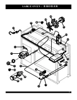
Page 23: ...1 2 3 4 6 7 5 8 9 10 1 11 12 13 15 16 18 19 20 17 21 25 24 23 22 LARGE OVEN BROILER 2 1 ...

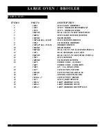
Page 24: ... 18020 01 BRASS ELBOW 11 90045 04 DUAL VALVE TO I R BURNER TUBING 12 13053 DUAL THERMAL GAS VALVE 13 90045 05 DUAL VALVE TO MANIFOLD TUBING 14 12023 OVEN BURNER 15 16009 02 I R BURNER IGNITER 16 16075 POWER CORD RANGES 16005 POWER CORD COOKTOPS 17 13003 L P N G REGULATOR 18 16127 CONVECTION SWITCH 19 16056 R CONVECTION BLADE R H 20 16053 MOTOR COOLING BLADE 21 16036 1 2 CONVECTION MOTOR 22 16127 O...

Page 25: ...AccesstheDual ThermalValvebyremovingthetop centralsectionofthecooktop maybeaGrill Griddle orOpenTopBurnersection dep e n d ingonthemodel Next removetheserviceaccesspanelinthe reartoexposetheThermalValve 7 IftheTh e rmalValveisOK Removethe w i resfromtheBroilerIgniterandchecktheigniter leadsforcontinuity Ifnone remove replaceigniter 8 IftheIgniterisOK ChecktheLive black andNeutral white ReturnWi re...

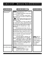
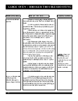
Page 26: ...sspanelinthe reartoexposetheThermalValve 7 IftheTh e rmalValveisOK Removethe w i resfromtheOvenBurnerIgniterandcheckthe igniterleadsforcontinuity Ifnone remove replace igniter 8 IftheIgniterisOK ChecktheLive black andNeutral white ReturnWi reforcontinuitytothe neutral white wireofthepowersupplycord IfOven continuestonotfunction checkallre l atedwiresfo r continuity re fertotheschematic 1 VerifyGas...

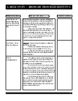
Page 27: ...ppears 1 Tocalibra tetheOvenTh e rmostat placea reliableoventhermometerontheOven Rotatethe thermostatto350 F After3bu rnercycles theoven shouldhavere a chedequilibrium 2 You llneedaknobwithaholedrilledthroughthe centertoallowaflat tippedscre wdrivertobeinsertedthroughit Withtheknobinplace insertathinblade fl at tipped s c rewd r iverthroughtheknobandnestitintothesmall slottedscrewinthethermostat i...

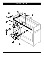
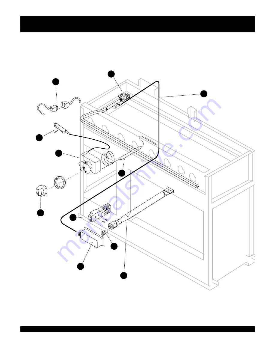
Page 28: ...1 2 3 4 7 5 6 8 9 11 10 SMALL OV E N 26 ...

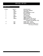
Page 29: ... SMALL IGNITER 5 13073 THERMAL VALVE 6 12023 OVEN BURNER 7 90045 06 GAS LINE TUBING 8 16077 FIBERGLASS SLEEVE 9 13005 48 ORIFICE HOOD NATURAL GAS ORIFICE PIN LP GAS 55 DMS INTEGRAL TO THERMAL VALVE 10 16075 POWER CORD RANGES 16005 POWER CORD COOKTOPS 11 13003 GAS REGULATOR usedonallRG 48 36 304 Cooktop48 36Models 27 SMALL OV E N ...

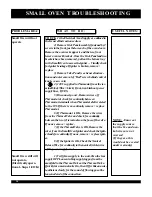
Page 30: ...replace Th e rmostat 6 IfTh e rmostatisOK Remove thewire s f romtheTh e rmalValveandcheckforcontinuity betweenthetwo 2 terminalsonthefaceofthevalve Ifnone remove replace 7 IftheTh e rmalValveisOK Removethe w i resfromtheSmallOvenIgniterandchecktheignit erleadsforcontinuity Ifnone remove replaceignit e r 8 IftheIgniterisOK ChecktheNeutra l ReturnWi reforcontinuitytotheneutral white wire ofthepowers...

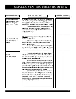
Page 31: ...leoventhermometerontheOven Rotatethe thermostatto350 F After3bu rnercycles theoven shouldhavere a chedequilibrium 2 You llneedaknobwithaholedrilledthroughthe centertoallowaflat tippedscre wdrivertobeinsertedthroughit Withtheknobinplace insertathinblade fl at tipped s c rewd r iverthroughtheknobandnestitintothesmall slottedscrewinthethermostat itmaybenecessaryto clearthescrewofasmallamountofsealant...

Reviews: