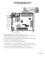
INPUT COMMANDS
(Continued)
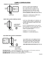
7, BACK-AWAY (FREE EXIT INPUT)
This input is used as a free exit input to open gate. When input
is active, gate will open and close immediately once input is removed. (EXAMPLE: Car pulls up to
exit loop, gate opens; car "backs-away" from exit loop and gate closes).
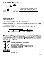
8, SHAD
- INTERLOCK (REDEFINED INPUT!!!) Used to monitor an auxiliary open limit switch of
another operator in the same lane. Interlock with memory feature (v5.20 or higher) see page 13.
9, 10, 11,12- COMMON
- These are the commons (0 VDC) to be used to activate above inputs.
Note: Above inputs are tied to LED indicators to show input command activity
.
ACCESSORY CONNECTIONS
These terminals will provide battery backed power to 24 VDC devices and are located at the bottom
of the electronic control board at terminals 1 and 2. Terminal 1 is 24 VDC (+) and number 2 is 0 VDC
(-). Peripheral CLASS 2 low voltage devices that require 24 VDC power maybe connected here (500
ma. maximum). EXAMPLE: Vehicle detector, radio receiver.
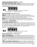
RELAY OUTPUT K1
-
(OPTION)
S1-6 off, S1-8 off
, relay will fire (latch) when gate is not closed.
S1-6 on S1-8 off
, relay will fire when arm is pushed up off of limit switch (use with slip clutch option).
and fires relay when a tail-gate is detected by the close loop -ANTI TAIL-GATE ALARM
S1-6 off S1-8 on
relay will pulse relay when arm reaches full open position.
S1-6 on S1-8 on
relay will only pulse when input is given to J5 1,2,3 inputs. (see page 14).
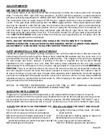
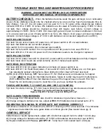
BATTERY INSTALLATION
HOOKING UP BATTERY LEADS-
ALWAYS HOOKUP AND TURN ON AC POWER
BEFORE
INSTALLING BATTERIES.
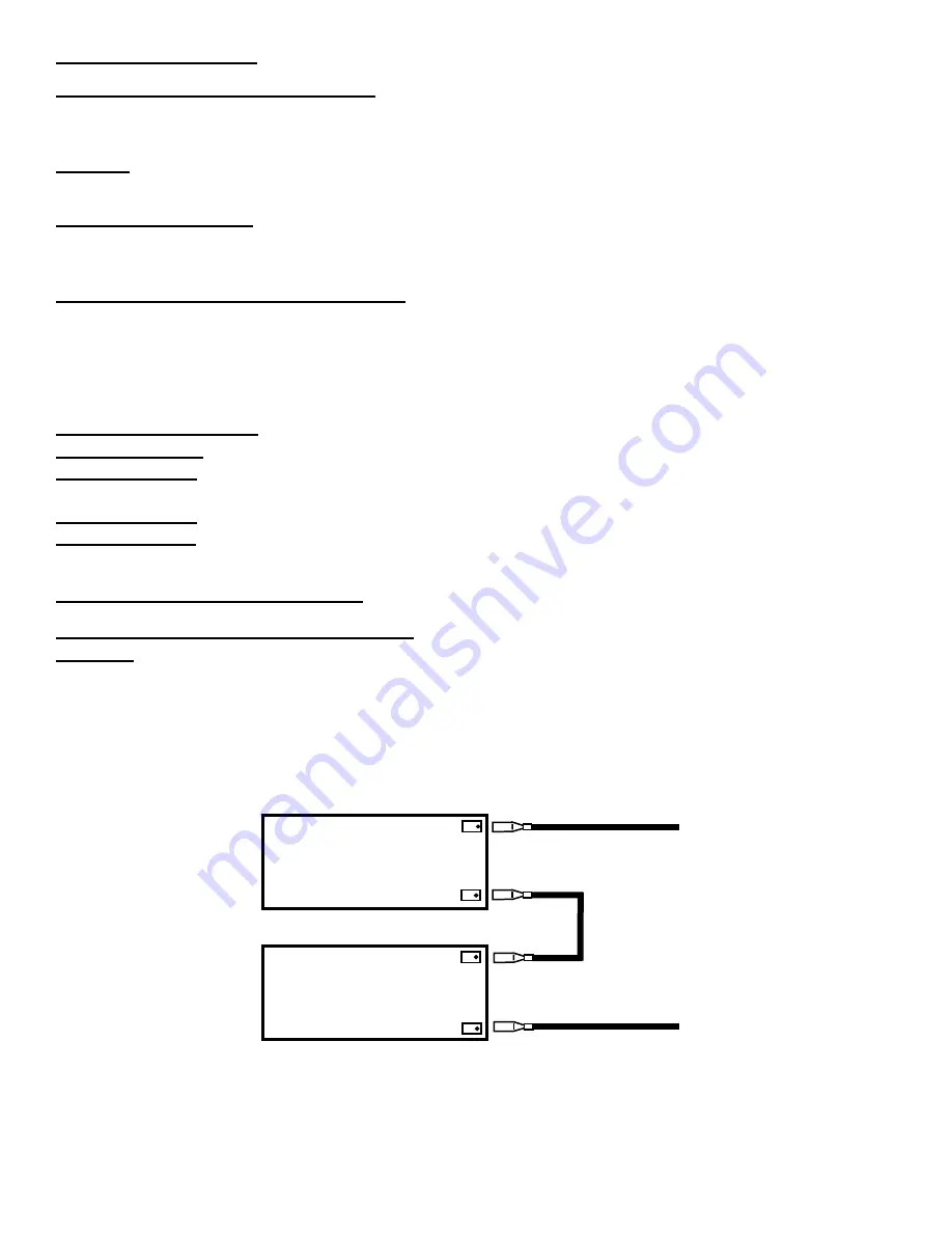
After turning on AC power, install two new, fully charged 12
volt DC batteries on shelf next to motor. Connect red lead from operator to the positive (RED +)
terminal of one battery and black lead from the operator to the (BLACK-) terminal of the OTHER
battery. Place the supplied jumper between the remaining terminals of each battery if one is not
already in place. See diagram. (USE YUASA BRAND PN#NP7-12)
WARNING-DO NOT RUN OPERATOR WITHOUT INSTALLING THE BATTERIES
+
-
+
-
12 VDC BATTERY
12 VDC BATTERY
RED LEAD
BLACK LEAD
JUMPER
Failure to install batteries correctly WILL cause damage and WILL not be covered by warranty.
PAGE 3


