dCS P8i
Mk2 User Guide
Guide for Software Issue 2.0x
Data Conversion Systems Ltd.
March 2011
Manual filename: dCS P8i User Guide v2_0x.docx
Page 10
English version
www.dcsltd.co.uk
Rear Panel
K
L
M N
O P Q R
S
T
V/W
U
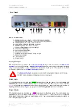
Key to the Rear Panel
K – Balanced analogue outputs L & R on XLR male connectors
L - Unbalanced analogue outputs L & R on RCA phono connectors
M – AES Digital Input on XLR female connector
N – AES Digital Output on XLR male connector
O – SPDIF Digital Input on RCA connector
P – SPDIF Digital Output on RCA connector
Q – Word clock Digital Input
R – Word clock Digital Output
S – Power link In and Out
T – Software Upgrade connector, 9-way ‘D’ type
V – Mains Fuse Holder
W – IEC Power Inlet
U – Power Switch
Analogue Outputs
The Player features separately buffered
Balanced Outputs
(K) on XLR connectors and
Unbalanced
Outputs
(L) on RCA connectors. The
Balanced Outputs
should be connected to true balanced inputs
only. If your preamplifier / power amplifier has unbalanced inputs (even if the inputs are on XLR
connectors), please use the
Unbalanced Outputs
instead.
!
The
Balanced Output
connectors are wired pin1=Screen, pin2=, pin 3=Signal-.
DO NOT connect Balanced Output pin 2 or pin 3 to ground.
Digital Inputs
The Digital Inputs are indicated by a GREEN background on the back panel. The unit features one
AES/EBU (M) and one SPDIF interface (O) on an RCA connector. They may be selected by the
Source
menu page (or the
Input+
button on the Premium Remote). These inputs give direct access to
the Player’s DAC section, they will accept up to 24 bit PCM digital data at 32, 44.1 or 48kS/s.
Digital Outputs
The Digital Outputs are indicated by a PINK background on the back panel. The unit features one
AES/EBU (N) and one SPDIF interface (P) on an RCA connector. These outputs carry CD format
PCM data (16 bits at 44.1kS/s) only when playing a CD. They are disabled when playing an SACD or
when using the Digital Inputs.


