background image

7

INSTRUCTIONS DE MONTAGE

MONTAGE ET INSTALLATION

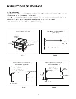
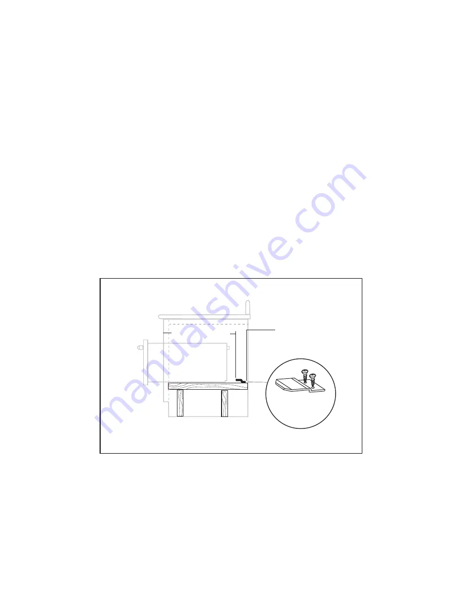
Les coins inférieurs arrière du boîtier doivent soutenir correctement l'arrière du chauffe-plats et les fixations
antibasculement.  Une prise c.a. de 120 V doit être située à moins de 92 cm (36 po) du centre arrière du chauffe-
plats.  

La section arrière inférieure de l'élément doit être fabriquée en contreplaqué plein ou de deux poutres 2 x 4. Il
comporte les clips de montage antibasculement et supporte le poids du tiroir chauffant, à savoir 90 lbs. (voir Fig.
06 et 07). Si on utilise deux poutres de 2 x 4, la distance entre leurs centres doit être de 20” pour pouvoir fixer le
tiroir chauffant.

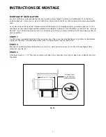
ÉTAPE 1

Use the screws provided and attach the mounting clips. They must be installed for anti-tip safety to the bottom
support at the back.  See placement dimensions in figure below (see Fig. 06 and 07).

ÉTAPE 2

Brancher le cordon d'alimentation dans une prise c.a.  Faire glisser le corps sur les clips de montage antibas-
culement (voir Fig. 07).

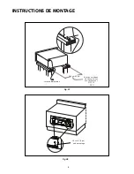
ÉTAPE 3

Utiliser les deux vis 1-1/2” fournies au travers des deux trous marqués (voir Fig. 08) pour fixer le devant du tiroir

chauffant.

Glissez le tiroir

sur les fixations

antibasculement

fixations

54,6 cm (21-1/2 po)

Fig. 06

Summary of Contents for Professional Warming Drawer WDT-30

Page 1: ...THE PROFESSIONAL WARMING DRAWER Installation Guide MODELS WDT 30 WDTI ...

Page 2: ......

Page 3: ... RISK OF INJURY TO PERSONS IN THE EVENT OF A WARMING DRAWER GREASE FIRE OBSERVE THE FOLLOWING SMOTHER FLAMES with a close fitting lid cookie sheet or metal tray then turn off the Warming Drawer BE CAREFUL TO PREVENT BURNS If the flames do not go out immediately EVACUATE AND CALL THE FIRE DEPARTMENT NEVER PICK UP A FLAMING PAN You may be burned DO NOT USE WATER including wet dishcloths or towels a ...

Page 4: ...F CONTENTS 2 SAFETY PRACTICES PRECAUTIONS 3 4 FEATURES 5 INSTALLATION INSTRUCTIONS Specifications 6 Mounting Installation 7 8 Custom Panel Installation WDTI 9 Cabinet Installation 10 SERVICE 11 WARRANTY 12 13 ...

Page 5: ...ce Children could be seriously injured if they should climb onto the appliance to reach these items Be certain to use only dry pot holders Moist or damp pot holders on hot surfaces may cause burns from steam Do not use a towel or other bulky cloth in place of pot holders Never store anything in the warming drawer Flammable materials can catch fire plastic items may melt or ignite and other types o...

Page 6: ... Service Technician Service Technicians must disconnect the power supply before servicing this appliance When using the warming drawer DO NOT TOUCH THE INTERIOR SURFACES or the exterior area immediately surrounding the door until it has had sufficient time to cool to avoid burn injuries Clean the warming drawer with caution Avoid steam burns do not use a wet sponge or cloth to clean the appliance ...

Page 7: ...Power Indicator Lens Thermostat Control Knob Power Indicator Light Stainless Steel Drawer Removable Stainless Steel Tray Model and Serial tag location on inside panel Vent Holes Fig 01 Not available on fully integrated model WDTI ...

Page 8: ...0 wide by 24 deep Power supply required 120Volts AC 5 amp min 15 amp maximum circuit requirement 1 1 2 min to bottom of countertop A 120 volt AC GFI outlet should be located below the Warming Drawer 2x4 s or similar support 10 1 16 25 3 4 1 16 24 20 10 1 2 29 11 16 23 1 2 25 1 16 28 3 16 POWER CORD 9 3 4 1 4 1 2 Fig 02 Fig 03 Fig 04 CUT OUT DIMENSIONS WARMING DRAWER DIMENSIONS FRONT VIEW WDT 30 DI...

Page 9: ... see Fig 06 and 07 If two 2x4 beams are used the distance between their centers must be 20 to be able to secure the Warming Drawer STEP 1 Use the screws provided and attach the mounting clips They must be installed for anti tip safety to the bottom support at the back See placement dimensions in figure below see Fig 06 and 07 STEP 2 Plug power cord into AC outlet Slide the body onto the anti tip m...

Page 10: ...8 INSTALLATION INSTRUCTIONS Center line to Center line for mounting clips for WDT 30 20 WDTI Fig 07 Fig 08 1 1 2 mounting screws Power cord Slot Slot ...

Page 11: ...n 9 16 to allow for clearance for the tips of the screws holding the drawer when the custom panel is mounted STEP 4 Center the provided paper front template on the back of the custom panel to drill or cut the clearance areas for the hardware holding the drawer Note the drill sizes and callouts are on the template STEP 5 Fasten the custom panel to the front face with the supplied screws as shown in...

Page 12: ...ig 10 DOUBLE Wall Oven and Warming Drawer Installation INSTALLATION INSTRUCTIONS warming drawer cutout single wall oven cutout microwave cut out 18 3 4 11 3 16 25 3 4 1 16 10 1 16 Fig 11 The floor of the opening should be constructed of plywood strong enough to support the weight of the oven or use 2x4 constructions see fig 02 CABINET INSTALLATION ...

Page 13: ...mber located at the front right hand side of the body of the drawer Serial Number located at the front right hand side of the body of the drawer Code located at the front right hand side of the body of the drawer Date of installation A brief description of the problem Your satisfaction is of the utmost importance to us If a problem cannot be resolved to your satisfaction please write to Customer C...

Page 14: ...e use All service under this Limited Warranty shall be provided by Fisher Paykel Appliances Inc or its Authorized DCS Service Agent during normal business hours HOW LONG DOES THIS LIMITED WARRANTY LAST Our liability under this Limited Warranty for the entire product expires One Year from the date of purchase of the Product by the first consumer Our liability under any implied warranties including ...

Page 15: ... you then have any questions about operating the Product need the name of your local DCS Authorized Service Agent or believe the Product is defective and wish service under this Limited Warranty please contact your dealer or call us at TOLL FREE 1 888 936 7872 or contact us through our web site www dcsappliances com You may be required to provide reasonable proof of the date of purchase of the Pro...

Page 16: ...NOTE 14 ...

Page 17: ...CHAUFFE PLATS PROFESSIONNEL Guide d installation MODÈLES WDT 30 WDTI ...

Page 18: ...e palette sangles avant d avoir inspecté l unité AVERTISSEMENT Le chauffe plats n est pas conçu pour être utilisé avec de l eau NE remplissez PAS le tiroir ou le logement du chauffe plats avec de l eau Cela pourrait créer un risque de choc et causer des blessures AVERTISSEMENT POUR RÉDUIRE LES RISQUES DE BLESSURES EN CAS DE FEU DE GRAISSE SUR LA CUISINIÈRE RESPECTEZ LES CONSIGNES SUIVANTES ÉTOUFFE...

Page 19: ...CURITé ET DE PRéCAUTION 3 4 CARACTERISTIQUES DU CHAUFFE PLATS 5 INSTRUCTIONS DE MONTAGE Specifications 6 Montage et Installation 7 8 Chauffe plats intégré 9 Four micro ondes et installation de chauffe plats 10 SERVICE 11 GARANTIE 12 13 ...

Page 20: ...ée ronde de la porte et la saisir pour ouvrir le chauffe plats Ils pourraient alors se blesser ou être brûlés sérieusement si l appareil est en fonctionnement et qu il est chaud AVERTISSEMENT Évitez de ranger des articles pouvant attirer les enfants dans l appareil au dessu ou à proximité Les enfants pourraient être blessés sérieusement s ils grimpent sur l appareil pour atteindre ces articles Uti...

Page 21: ...la vapeur avant de retirer ou d introduire des aliments Ne réparez pas ni ne remplacez aucune pièce de cet appareil sauf indication contraire du manuel Tout autre travail d entretien doit être confié à un technicien qualifié Celui ci doit débrancher le bloc d alimentation avant de travailler sur l appareil Durant l utilisation du chauffe plats afin d éviter de vous brûler NE TOUCHEZ PAS LES SURFAC...

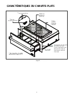
Page 22: ...uette de modèle et de série situé sur le panneau droit intérieur de la cavité du tiroir derrière le côté du tiroir droit Trous de ventilation Tiroir en acier inoxydable Voyant d alimentation Plateau en acier inoxydable amovible Bouton de réglage du thermostat Lentille du voyant d alimentation Bouton Humide Croustillant ...

Page 23: ...m requis 3 8 cm 1 1 2 po min jusqu au bas du dessus de comptoir Une prise d alimentation CA de 120 volts doit être située au dessous du chauffe plats 2x4 ou support similaire 25 4 1 5 mm 10 1 16 po 65 4 1 5 mm 25 3 4 1 16 po 61 cm 24 po 50 8 cm 20 po Fig 02 DIMENSIONS DES DéCOUPES Fig 03 Fig 04 DIMENSIONS DU CHAUFFE PLATS VUE AVANT 59 7 cm 23 1 2 po 63 7 cm 25 1 16 po 71 6 cm 28 3 16 po cordon d a...

Page 24: ...voir Fig 06 et 07 Si on utilise deux poutres de 2 x 4 la distance entre leurs centres doit être de 20 pour pouvoir fixer le tiroir chauffant ÉTAPE 1 Use the screws provided and attach the mounting clips They must be installed for anti tip safety to the bottom support at the back See placement dimensions in figure below see Fig 06 and 07 ÉTAPE 2 Brancher le cordon d alimentation dans une prise c a ...

Page 25: ...8 INSTRUCTIONS DE MONTAGE WDT 30 WDTI De la ligne médiane à la ligne médiane pour les fixations 50 8 cm 20 po Fig 07 Fig 08 3 8 cm 1 1 2 po vis de montage cordon d alimentation ...

Page 26: ...tés des vis retenant le chauffe plats une fois le panneau posé ÉTAPE 4 Centrer le gabarit avant en papier fourni sur le dos du panneau personnalisé pour percer ou couper les zones à dégager pour la visserie maintenant le tiroir Remarque les dimensions de perforation et les références se trouvent sur le gabarit ÉTAPE 5 Fixez le panneau à l aide des vis fournies tel qu indiqué à la fig 09 Fig 09 65 ...

Page 27: ...6 mm 25 3 4 1 16 po 65 4 cm 1 6 mm 25 3 4 1 16 po 25 4 cm 1 6 mm 10 1 16 po 25 4 cm 1 6 mm 10 1 16 po 28 4 cm 11 3 16 po 28 4 cm 11 3 16 po Four double et installation de chauffe plats Four simple micro ondes et installation de chauffe plats Le fonds de l ouverture doit être fait d un contre plaqué assez solide pour supporter le poids du four et sa charge ou utiliser une construction 2 x 4 voir fi...

Page 28: ... tiroir derrière le côté du tiroir droit Numéro de série situé sur le panneau droit intérieur de la cavité du tiroir derrière le côté du tiroir droit Code situé sur le panneau droit intérieur de la cavité du tiroir derrière le côté du tiroir droit Date d installation Brève description du problème Votre satisfaction revêt la plus haute importance pour nous Si un problème n est pas résolu à votre en...

Page 29: ...ormales QUELLE EST LA DURÉE DE CETTE GARANTIE LIMITÉE Notre responsabilité en vertu de cette garantie limitée concernant l intégralité du produit expire UN AN à partir de la date d achat du produit par le premier acheteur Notre responsabilité en vertu de toute garantie implicite y compris la garantie implicite de qualité marchande la garantie tacite selon laquelle le produit est approprié pour un ...

Page 30: ...que vous cherchez le nom de l agent de service DCS agréé local ou que pensez que le produit est défectueux et désirez le faire réparer dans le cadre de cette garantie limitée veuillez contacter votre distributeur ou nous appeler au numéro suivant NUMÉRO SANS FRAIS 1 888 936 7872 ou contactez nous par l intermédiaire de notre site Web www dcsappliances com Vous devrez peut être présenter une preuve...

Page 31: ......
Page 32: ...w dcsappliances com As product improvement is an ongoing process we reserve the right to change specifications or design without notice Nous améliorons constamment ses produits et se réserve le droit de modifier les spécifications ou la conception de ses produits sans aucun préavis P N 241266 Rev B Litho in USA 08 2008 ...

Reviews: