background image


1

LOCATION OF CONTROLS 


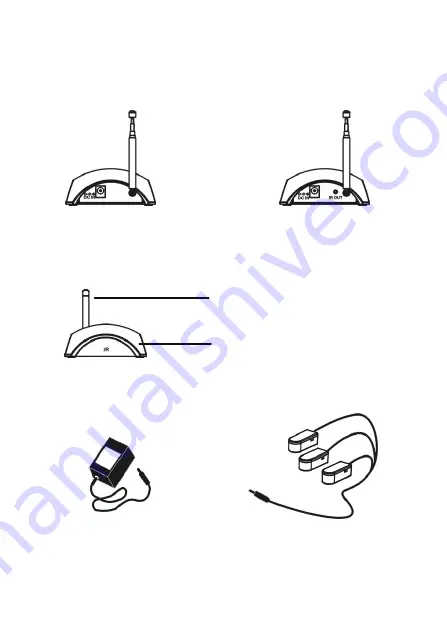
Transmitter Side


Receiver Side 


Accessories 


DC 12 V   
AC 120V 
Adaptor x2 

Infrared  Extender X 3  
1,1.5,2m in length 

DC Power  

DC Power   IR Probe 

Infrared Remote  
Control Antenna 
 
 
Remote Control 
Indicators &  
IR Transmitter/Receiver 

Transmitter and  
Receiver Front


Summary of Contents for DIR-300V

Page 1: ...DIGITAL REMOTE CONTROL EXTENDER MODEL DIR 300V OWNERS MANUAL ...

Page 2: ...ide Receiver Side Accessories DC 12 V AC 120V Adaptor x2 Infrared Extender X 3 1 1 5 2m in length DC Power DC Power IR Probe Infrared Remote Control Antenna Remote Control Indicators IR Transmitter Receiver Transmitter and Receiver Front ...

Page 3: ... to try to correct the interference by one or more of the following measures z Reorient or relocate the receiving antenna z Increase the distance between the affected equipment and the receiver z Connect the affected equipment to an outlet on a circuit which is different from than the one the receiver is connected to z Consult the dealer or an experienced radio TV technician for help IMPORTANT SAF...

Page 4: ...llite receivers etc virtually anywhere in the home Applications The remote operation of electronics products that utilize IR Infrared remote control technology such as Satellite Receivers Television VCR s Video Cassette Recorders CDs Compact Disc DVD s Digital Video Disc LDP s Laser Disc Players Cable Converter Boxes Audio Hi Fi Stereo Systems Wireless Video Sender Systems Any IR Remote Controlled...

Page 5: ...2 DSS Satellite Receiver with remote control Wall DIR 300V Receiver IR Remote Control DIR 300V Transmitter Probe Stereo Wire to Extension Speaker 2nd TV DSS or Satellite Receiver DIR 300V Receiver DIR 300V Transmitter IR Remote Control Wall IR Signal RF Signal ...

Page 6: ...is affixed toward IR sensor receiving Window with proper position within 0 5M and working angles 15 Keep Vertical Power Adaptor Using IR Antenna Working without extender probe Working without extender probe Not less than 0 3M and not more than 6M Working Angle not more than 15 Working Angle not more than 15 Side View 5 7 M 6 M 0 3 ...

Page 7: ...smitter Picture 6 Picture 7 Picture 5 Antenna Power Adaptor Working Angle not more than 15 Remote Control Keep Vertical Distance Not less than 0 3M and not more than 7M Working Angle not more than 15 Antenna ...

Page 8: ...ew Do not use harsh chemicals cleaning solvents or strong detergents Specifications Operating Voltage 120 VAC 50Hz 60Hz DC 12V 250mA Power Consumption pair 3 Watts Max Transmission Frequency 433 92MHz 1MHz Power Gain 10dBm Effective operating range about 100M clear line of sight Warning Changes or modifications to this unit not expressly approved by the party responsible for compliance could void ...

Reviews: