15
De Gier B.V., Westlandseweg 9, 2291 PG WATERINGEN, THE NETHERLANDS,
+31 (0)174 292089, sales@degierdrivesystems.com, www.degierdrivesystems.com
Versie 1 – 2020 / 03 / 01
4. Setting the limit switches
Please note!
Do not keep loose parts or documents underneath the stainless-steel protective plate. This could impede
the functioning of the limit switch system!
Adjustment procedure
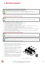
1. Remove the stainless-steel protective plate. The limit switch mechanism is now visible.
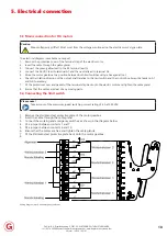
2. Check whether the adjustment rings (C) are loosely on the knurled nuts (D) by manually moving the nuts
across the switch axle (A). If this is not the case, unscrew the set screws one turn (do not remove them).
3. Use a hexagonal tool to drive the motor gearbox via the rear of the electric motor to determine which
working switch (S11 or S12) marks the start and end position in your application.
4. Move the motor gearbox to the start position by using the hexagonal tool. See the image on the next page.
Caution
When driving the electric motor by means of a hexagonal tool, a maximum speed of 250 RPM should
be observed to protect the hexagonal socket on the rear of the electric motor shaft.
5. Hand-tighten the associated knurled nut (D) against its stop nut (B).
6. Place the included hexagonal wrench (X) into the long set screw (H) and turn the adjustment ring (C) across
the knurled nut (D), so the switch spring is being pulled away from the plastic housing, until you hear one soft
click. Subsequently tighten the long adjusting screw onto the knurled nut using a torque of 2 Nm.
7. Tighten the short set screw (G) of the previously adjusted knurled nut (E), also applying a torque of 2 Nm.
8. Move the motor gearbox to the other end position by use of a hexagonal tool.
9. Repeat steps 5 to 7 to adjust the other working switch.
10. Place the stainless-steel protective plate back onto the motor gearbox and re-tighten the two screws.
11. Keep this manual with adjustment instruction in a suitable location.
Tip
To avoid future errors, mark which working limit switch corresponds to the start and end position!


