De Gier B.V., Westlandseweg 9, 2291 PG WATERINGEN, THE NETHERLANDS,
+31 (0)174 292089, sales@degierdrivesystems.com, www.degierdrivesystems.com
Versie 1 – 2020 / 03 / 01
25
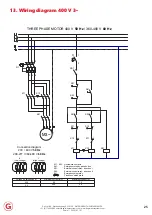
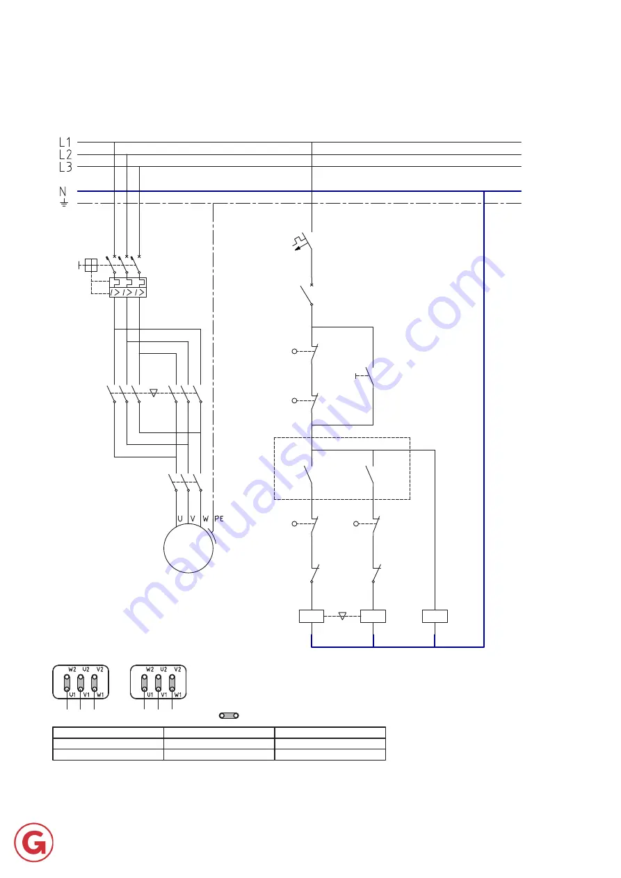
13. Wiring diagram 400 V 3~
K41
K12
K11
2
1
F1
Q1/1
S21
S22
S51
S52
S11
S12
K12
K11
K11
K12
S41
K41
Q1
1
2
3
4
5
6
M3~
0.5
1.5
Maximum current [A]
200
24
50
230
Minimum current [mA]
Voltage on limitswitch [V]
S11 - S22: Limitswitch contacts
S41:
Emergency stop by-pass button
S51:
External control relay - direction
I
S52:
External control relay - direction
II
K41:
Emergency stop relay
Fixed connection plate
Connection diagram
230 / 400 V
50 Hz
208-277 / 360-480 V
60 Hz
Y
(High voltage)
Δ
(Low voltage)
THREE PHASE MOTOR 400 V
50 Hz
/ 360-480 V
60 Hz


