115.6031.0
- 10 -
1.3
Component Description
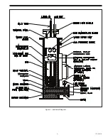
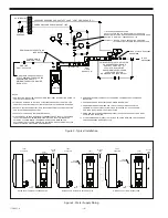
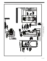
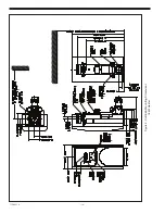
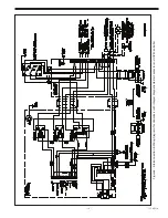
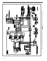
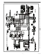
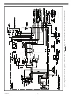
Refer to Figures 1, 2, 3, 4 and 5 to supplement the following text.
1.3.1 General
In addition to the components described in Section 1.3.2, which comprise the Basic Vaporizer Unit,
all Vaporizer Systems should be piped and valved to include the auxiliary components as shown in
Figures 2 and 3.
1.3.2 Basic Vaporizer Unit
1.3.2.1 Water Chamber
The water chamber provides uniform distribution of heat around the outer surface of the
vaporizing chamber wall. The chamber’s outer surface is covered with closed cell foam
insulation to minimize radiant and convective heat losses.
1.3.2.2 Vaporizing Chamber
The vaporizing chamber receives the liquid chemical from its source and converts it into the
gaseous state at a rate equal to the demands of the using system. This chamber contains an inlet
tube and superheat baffle which function as described below to provide the essential
operating requirements of the vaporizing system.
a.
Inlet Tube: The inlet tube, which extends to the lower portion of the chamber, serves to
provide both forward and reverse flow of liquid chemical to and from the chamber; thereby,
automatically regulating the level of liquid chemical in the chamber to increase and decrease
the liquid contact area, and hence the rate of evaporation, in accordance with the demands of
the overall system.
b.
Superheat Baffle: The superheat baffle, which extends a short distance downward from the top
of the chamber, serves to force the gas to travel along the hot wall of the chamber as it passes
from the surface of the liquid to the outlet; thereby, superheating the gas, i. e., increasing its
heat content at the existing pressure within the chamber, prior to its discharge to the gas
distribution system.
1.3.2.3 Water Level Gauge
The water level gauge provides visual indication of the water level in the water chamber.
1.3.2.4 Electric Immersion Heater
The electric immersion heater supplies the heat required to maintain the temperature of the water
in the water chamber at the desired operating value.
1.3.2.5 Magnetic Heater Contactor
The magnetic heater contactor acts in response to the water temperature controller to energize and
de-energize the electric immersion heater. This component, although essential to the operation
of the Vaporizer, may not have been supplied unless specifically requested. This may have been
due to site specific electrical design criteria requiring that the contactor be mounted in a centrally
located motor control center.
Summary of Contents for Capital Controls 71V3B Series
Page 1: ... 1 115 6031 0 Instruction Manual Series 71V3B Electrically Heated Vaporizer CAPITAL CONTROLS ...
Page 9: ... 9 115 6031 0 Figure 1 Sectional Diagram ...
Page 17: ... 17 115 6031 0 Figure 4 Outline Mounting Dimensions 12 kW 15 kW Heaters ...
Page 18: ...115 6031 0 18 Figure 5 Outline Mounting Dimensions 18 kW Heater ...


